Warnings and cautions, Related products, Product compatibility – Rockwell Automation 1771-IR , D17716.5.76 RTD INPUT MODULE User Manual
Page 7
Using This Manual
Chapter 1
1Ć2
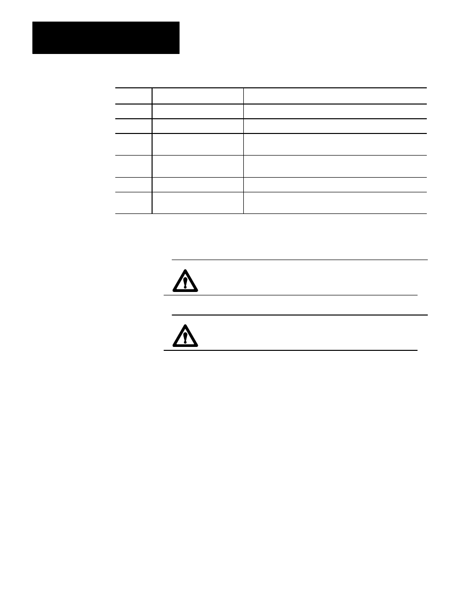
Chapter
Topics Covered
Title
Appendix A Specifications
Your module's specifications
Appendix B Programming Examples
Appendix C Data Formats
Information on BCD, signed magnitude (12-bit) binary, and 2's
complement binary
Appendix D Block Transfer with Mini-PLC-2
and Mini-PLC-2/20
How to use GET-GET instructions for block transfer with Mini-PLC-2
and Mini-PLC-2/20 processors
Appendix E 2 and 4-wire RTD Sensors
Shows wiring connections for 2 and 4-wire sensors
Appendix F Differences Between Series A
and B
Identifies major differences between the series A version and the
series B version of the RTD module.
This manual contains warnings and cautions.
WARNING: A warning indicates where you may be injured if you
use your equipment improperly.
CAUTION: Cautions indicate where equipment may be damaged
from misuse.
You should read and understand cautions and warnings before performing the
procedures they precede.
You can install your input module in any system that uses Allen–Bradley
programmable controllers with block transfer capability and the 1771 I/O
structure.
Contact your nearest Allen–Bradley office for more information about your
programmable controllers.
This input module can be used with any 1771 I/O chassis. Communication
between the discrete analog module and the processor is bidirectional. The
processor block–transfers output data through the output image table to the
module and block–transfers input data from the module through the input image
table. The module also requires an area in the data table to store the read block
and write block data. I/O image table use is an important factor in module
placement and addressing selection. The module’s data table use is listed in the
following table.
Warnings and Cautions
Related Products
Product Compatibility