Default configuration for the rtd input module, Chapter summary – Rockwell Automation 1771-IR , D17716.5.76 RTD INPUT MODULE User Manual
Page 30
Module Configuration
Chapter 5
5Ć6
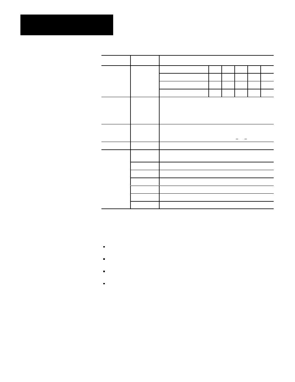
Word
Description
Bits
1.5
0
1
1
1
1
Word 1 (cont.)
2.0
1
0
1
0
0
2.5
1
1
0
0
1
3.0
1
1
1
1
0
Word 2
If bit 10 is set in word 1, and temperature readings are desired, word
2 must also be used. Enter the exact resistance of 10 ohm RTD at
25
o
C in BCD. Range is 9.00 to 11.00 ohms. Values less than 9.00
ohms or greater than 11.00 ohms will default to 10.00 ohms.
Non-BCD values will also default to 10.00 ohms.
Words 3-8
Individual channel bias words entered in BCD. This value is
subtracted from the channel data in the BTR. The bias value is
always a positive number. Bias value range is 0 Words 9-14 Individual channel calibration words. Word 15 Auto-calibration request word - used to automatically calibrate selected channels and save the calibration constants in EEPROM. Bit 00 Offset calibration complete Bit 01 Gain calibration complete Bit 02 Save complete Bit 06 EEPROM fault Bit 07 Faulty calibration (no save) Bits 10-15 Channel failed calibration If zeroes are written to the module in all configuration positions, the module BCD format 100 ohm platinum RTD temperature in degrees C real time sampling = inhibited (sample time = 50msec) In this chapter you learned how to configure your module’s hardware, condition Default Configuration for the RTD Input Module Chapter Summary
will default to:
your inputs and enter your data.