Rockwell Automation 1771-IR , D17716.5.76 RTD INPUT MODULE User Manual
Page 10
Overview of the RTD Input Module
Chapter 2
2Ć2
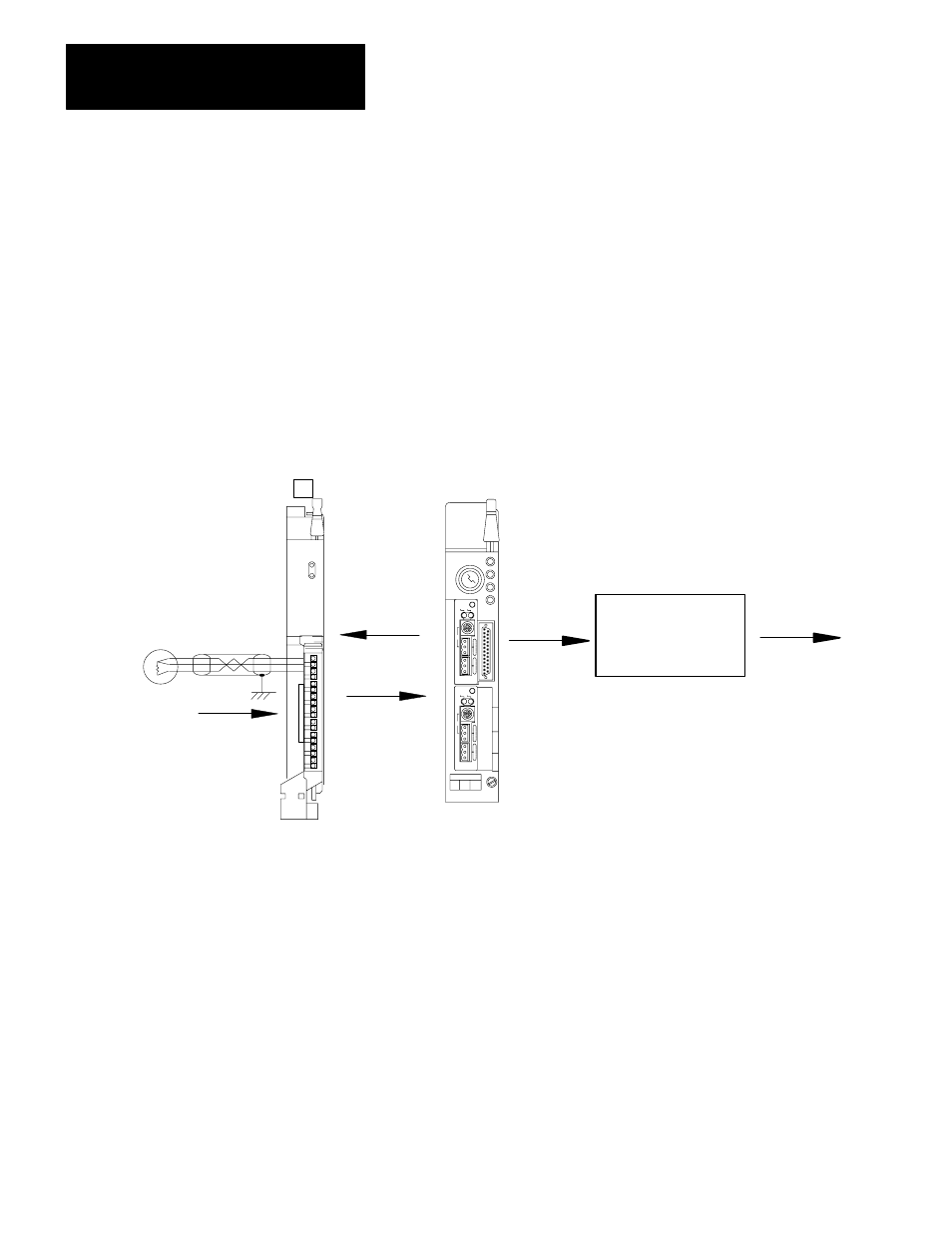
The processor transfers data to and from the module using block transfer write
(BTW) and block transfer read (BTR) instructions in your ladder diagram
program. These instructions let the processor obtain input values and status
from the module, and let you establish the module’s mode of operation (figure
2.1).
1.
The processor transfers your configuration data and calibration values to
the module using a block transfer write instruction.
2.
External devices generate analog signals that are transmitted to the
module.
Figure 2.1
Communication Between Processor and Module
Memory
User Program
To Output Devices
PC Processor
(PLC-5/40 Shown)
RTD Input Module
1771-IR Series B
BTW 1
BTR 4
5
6
2
3
12933-I
18
16
14
12
10
8
6
4
2
RTD
3.
The module converts analog signals into binary or BCD format, and
stores theses values until the processor requests their transfer.
4.
When instructed by your ladder program, the processor performs a read
block transfer of the values and stores them in a data table.
5.
The processor and module determine that the transfer was made without
error, and that input values are within specified range.
6.
Your ladder program can use and/or move the data (if valid) before it is
written over by the transfer of new data in a subsequent transfer.
How Analog Modules
Communicate with
Programmable Controllers