Chapter summary, Troubleshooting chapter 8, Status reported in word 9 – Rockwell Automation 1771-IR , D17716.5.76 RTD INPUT MODULE User Manual
Page 44
Troubleshooting
Chapter 8
8Ć3
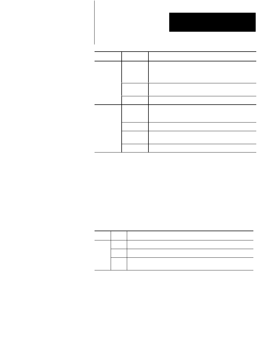
Word
Indication
Bit
Word 1 (cont.)
10-15
Data overrange. Bit 15 corresponds to channel 6, bit 14 corresponds
to channel 5, and so on. If input connections and resistances are
correct, this status may indicate a failed RTD functional analog block
(RTD FAB).
16
RTS timed out. The module updated its inputs before the processor
read them.
17
Not used.
2
00-05
Indicates that the default bias of 1000.0 has been subtracted from the
measured value. If sending binary data, no overflow occurs unless
there is a hardware malfunction.
06-07
Not used
10-15
Data sign bits formatted for BCD or signed magnitude. Bit 10
corresponds to channel 1, bit 11 to channel 2, and so on.
16-17
Not used
Status Reported in Word 9
Design your program to monitor status bits in word 9 during calibration, and to
take appropriate action depending on your requirements. You may also want to
monitor these bits while troubleshooting with your industrial terminal. The
module sets a bit (1) to indicate it has detected one or more of the following
conditions.
Table 8.C
Status Reported in Word 13
Word
Bit
Condition
9
6
The EEPROM could not be written.
7
Channel(s) could not be calibrated as indicated by bits 10 through 15 respectively.
10-15
Bit 10 (channel 1) through bit 16 (channel 6) could not be calibrated. Check field
wiring arm connections and source for proper resistance.
In this chapter, you learned how to interpret the LED status indicators and
troubleshoot your input module.
Chapter Summary