Troubleshooting chapter 8, Status reported in words 1 and 2 – Rockwell Automation 1771-IR , D17716.5.76 RTD INPUT MODULE User Manual
Page 43
Troubleshooting
Chapter 8
8Ć2
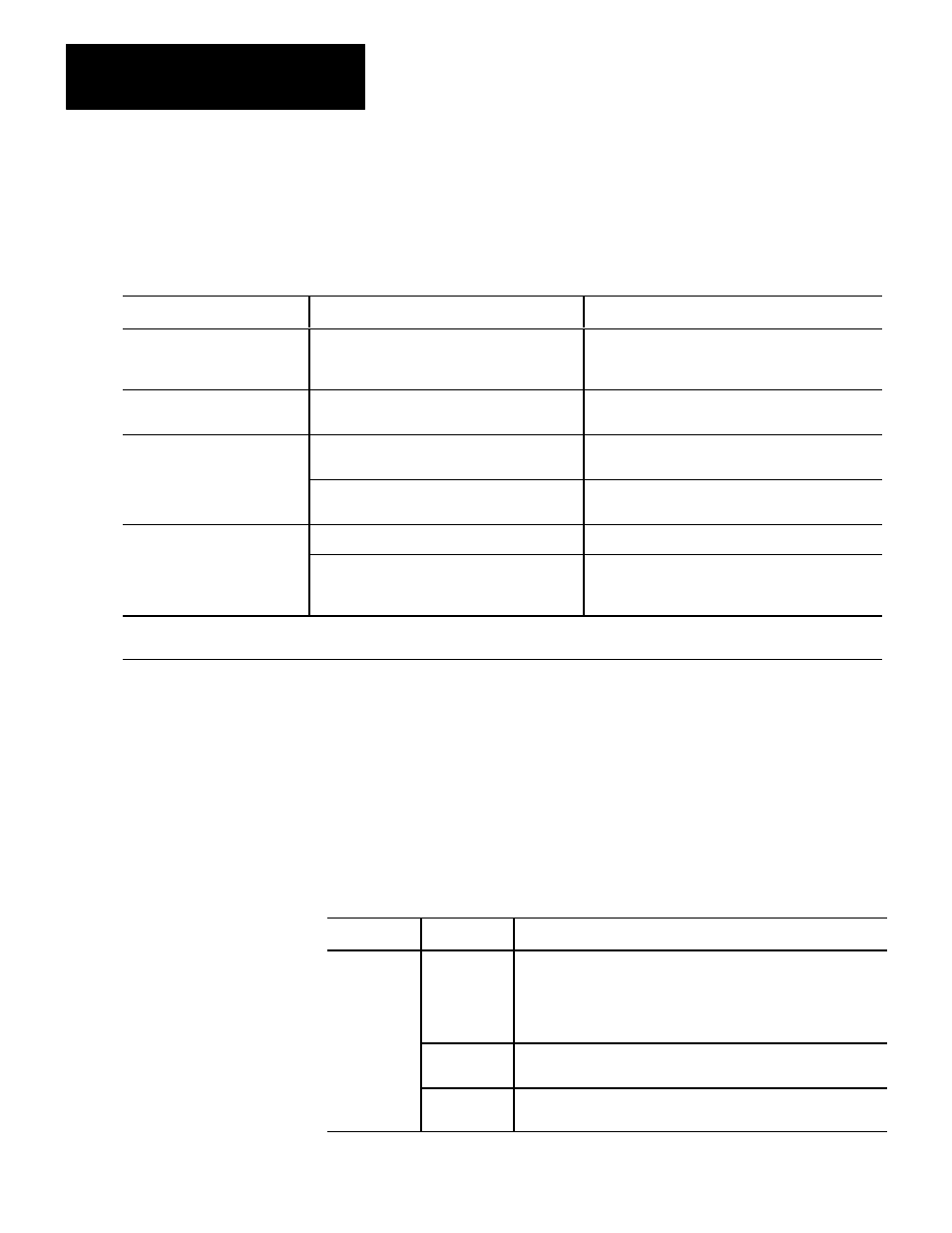
Table 8.A shows LED indications and probable causes and recommended
actions to correct common faults.
Table 8.A
Troubleshooting Chart for the RTD Input Module (1771-IR/B)
Indication
Probable Cause
Recommended Action
Both LEDs are OFF
No power to module
Possible short on the module
LED driver failure
Check power to I/O chassis. Recycle as necessary.
Replace module.
Red FLT LED ON and
Green RUN LED is ON
Microprocessor, oscillator or EPROM failure
Replace module.
Red FLT LED ON
If immediately after power-up, indicates RAM or
EPROM failure.
1
Replace module.
If during operation, indicates possible
microprocessor or backplane interface failure.
1
Replace module.
Green RUN LED is flashing
Power-up diagnostics successfully completed.
Normal operation.
If LED continues to flash, and write block transfers
(BTW) cannot be accomplished, you have a
possible interface failure.
Check ladder logic program. If correct, replace module.
1
When red LED is on, the watchdog timer has timed out and backplane communications are terminated. Your user program should monitor
communication.
Status Reported in Words 1 and 2
Design your program to monitor status bits in words 1 and 2, and to take
appropriate action depending on your application requirements. You may also
want to monitor these bits while troubleshooting with your industrial terminal.
The module sets a bit (1) to indicate it has detected one or more of the following
conditions.
Table 8.B
Status Reported in Words 1 and 2
Word
Bit
Indication
1
00-05
Data underrange. Bit 05 corresponds to channel 6, bit 04 corresponds
to channel 5, and so on. If input connections and resistances are
correct, this status may indicate failed communications between the
channel and microprocessor. If all channels are underrange, a blown
fuse or failed dc-dc converter may be the cause.
06
Successful power-up and module is waiting for configuration data. Bit
06 is reset after the first successful block transfer write.
07
EEPROM calibration constants could not be read. The module will
continue to operate but readings may be inaccurate.