Rockwell Automation 1771-IR , D17716.5.76 RTD INPUT MODULE User Manual
Page 39
Module Calibration
Chapter 7
7Ć6
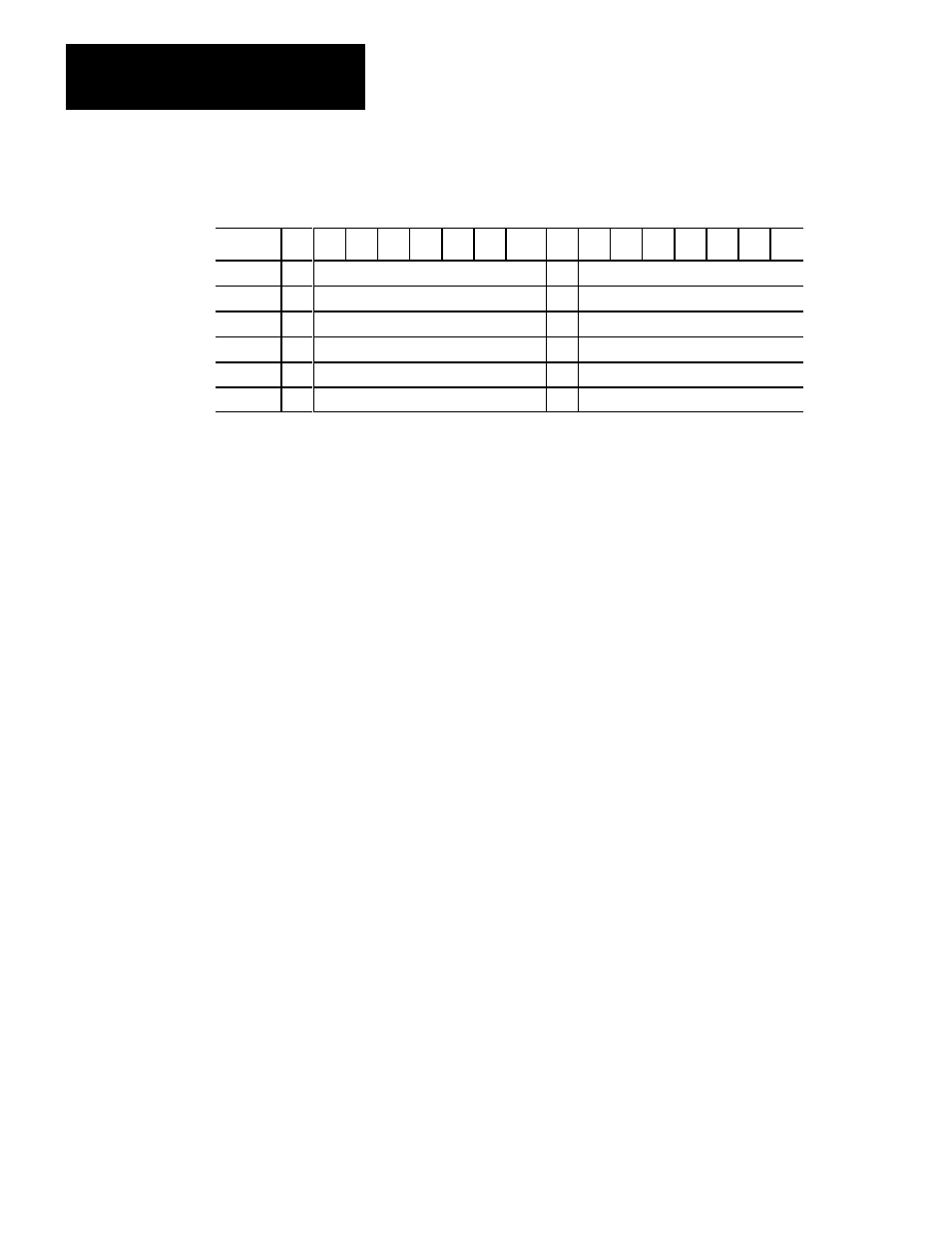
Table 7.C
Module Calibration Words
Word/Bit
17
16
15
14
13
12
11
10
07
06
05
04
03
02
01
00
9
S
Channel 1 Offset
S
Channel 1 Gain
10
S
Channel 2 Offset
S
Channel 2 Gain
11
S
Channel 3 Offset
S
Channel 3 Gain
12
S
Channel 4 Offset
S
Channel 4 Gain
13
S
Channel 5 Offset
S
Channel 5 Gain
14
S
Channel 6 Offset
S
Channel 6 Gain
Enter the information for each byte in signed magnitude binary format. In each
byte, the most significant bit (bits 17, 7) is a polarity bit. When the polarity bit
is set (1), the module anticipates a negative calibration value.
A negative calibration value means that your readings are too high and you
want to subtract a corrective amount from that reading.
A positive calibration value means that your readings are too low and you want
to add a corrective amount to that reading.
Important: If you have a spare field wiring arm. you may want to temporarily
switch it with the module’s present wiring arm. You can use this spare arm for
test purposes in order to avoid disconnecting your RTD wiring.
Offset Calibration
1. Attach the 1.00 ohm, 1% resistors as shown in Figure 7.1.
2. Examine word 3 (channel 1 data) in the read block transfer file. Note the
value. It should be around 1.00 (100 for 10 mohm resolution; 33 for 30
mohm resolution).
3. Examine word 9 of the write block transfer data file. Bits 16–10 make up
the offset correction byte. Bit 17 is the sign bit.
4. Subtract the data value that you noted in step 2 from 100. The difference
should be within +127 to –127. If it is not, the required correction is
beyond the range of software calibration. If the difference is within range,
input the difference (positive or negative), in binary form, in bits 17–10 of
word 9 in the write block transfer file.
For example, if, at 1.00 ohm, word 3 of the read block transfer data file
shows 147, you would subtract 147 from 100, which equals –47. You
would then enter 10101111 (–47) in the upper byte of word 9. The leading
1 (bit 17) is the polarity bit. It indicates a negative correction factor. That