Rockwell Automation 1747-PCIS API Software - Open Controller User Manual
Page 92
Publication 1747-UM002A-US-P - June 2000
6-32 Library of Routines
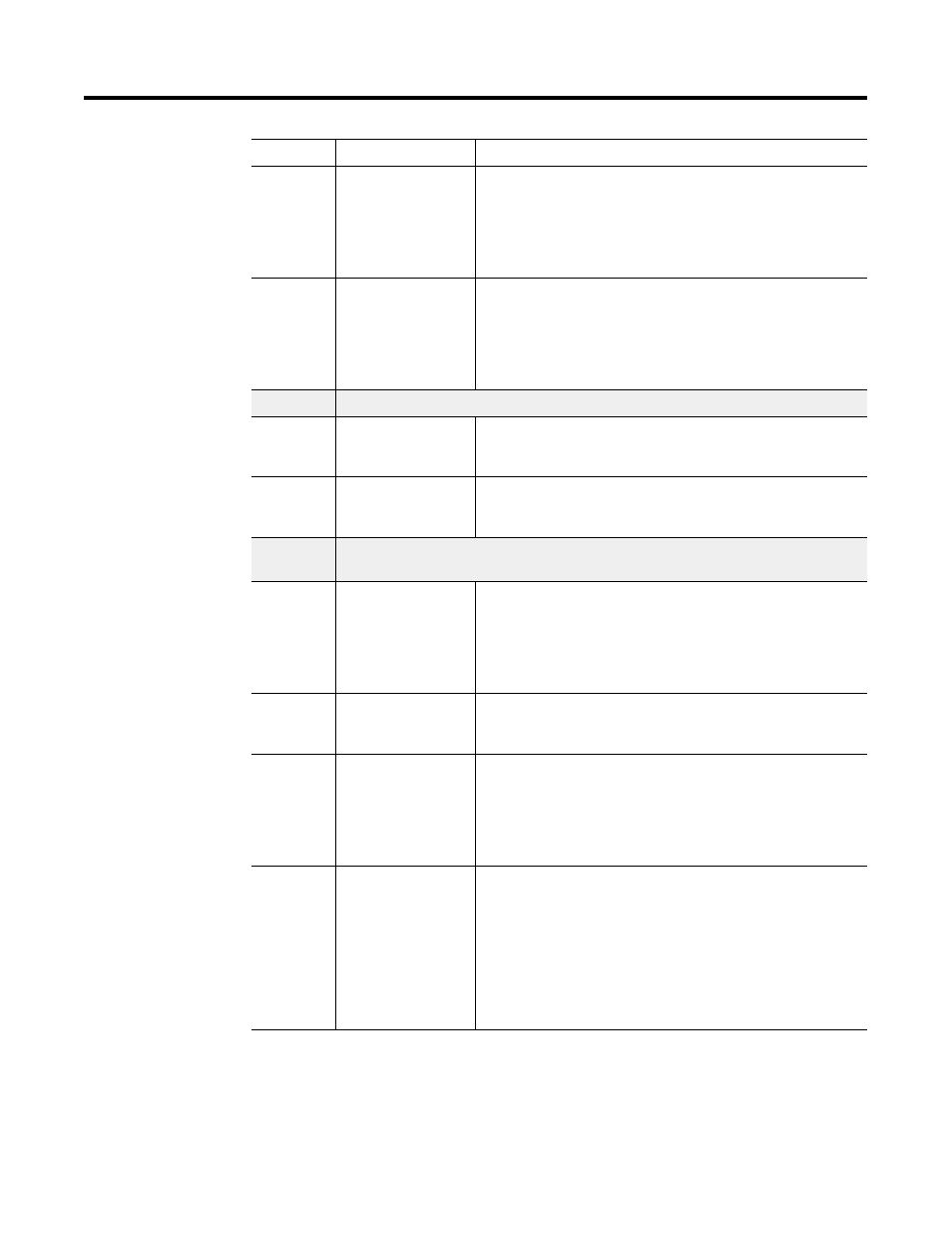
7 to 8
status
I/O interrupt pending
These two words are bit-mapped to the 30 I/O slots. Bits 7/1
through 8/14 refer to slots 1-30. Bits 7/0 and 8/15 are not used.
The pending bit associated with a slot is set when an interrupt
request is received from that slot. This bit is set regardless of the
state of the I/O interrupt enabled bit (wee word 9 and 10).
9 to 10
status
I/O interrupt enabled
These two words are bit-mapped to the 30 I/O slots. Bits 9/1
through 10/14 refer to slots 1-30. Bits 9/0 and 10/15 are not used.
The corresponding enable bit must be set in order for an I/O
interrupt received priority message to be generated when a module
issues an interrupt request.
11/0 to 11/8 reserved
11/9
status
I/O scan toggle bit
This bit is cleared upon entry into Scan mode and is toggled
(changes state) at the end of every I/O scan.
11/10
dynamic configuration
DII reconfiguration bit
If the bit is set by the host, the DII function will reconfigure itself at
the end of the next I/O scan.
11/11 to 11/
15
reserved
12
status
Last I/O scan time
This word indicates the current observed interval between
consecutive I/O scans. The interval time is reported in units of 250
ms.
Resolution of the last scan time is +0 to -250 ms. For example, the
value 10 indicates that 2.25-2.5 ms was the last scan time.
13
dynamic configuration
DII function enable
A value of zero written to this word will disable the discrete input
interrupt function. Any non-zero value will enable the function.
14
dynamic configuration
DII slot number
This word is used to configure the DII function. The slot number
(1-30) that contains the discrete I/O module should be written to
this word. The scanner will fault if the slot is empty or contains a
non-discrete I/O module. This word is applied upon detection of the
DII reconfigure bit 11/10 or upon entry to Scan mode.
15
dynamic configuration
DII bit mask
This word contains a bit-mapped value that corresponds to the bits
to monitor on the discrete I/O module. Only bits 0-7 are used in the
DII function. Setting a bit indicates that it is to be included in the
comparison of the discrete I/O module’s bit transition to the DII
compare value (word 16). Clearing a bit indicates that the transition
state of that bit is a “don’t care.”
This word is applied upon detection of the DII reconfigure bit 11/10
and at the end of each I/O scan.
Word/Bit:
Classification:
Description: