Rockwell Automation 1771-IFE ANALOG INPUT MODULE User Manual
Page 55
7–5
Troubleshooting Your Input Module
Publication 1771Ć6.5.115 - February 1999
BT9:0
EN
DN
1
ER
EN
DN
ER
BTW
BLOCK TRANSFER WRITE
RACK:
GROUP:
MODULE:
CONTROL BLOCK:
DATA FILE:
LENGTH:
CONTINUOUS:
N
BTR
BLOCK TRANSFER READ
RACK:
GROUP:
MODULE:
CONTROL BLOCK:
DATA FILE:
LENGTH:
CONTINUOUS:
N
N7:0
0
00
0
0
BT9:0
N7:40
0
00
0
0
BT9:1
EN
BT9:1
EN
BT9:1
EN
BT9:0
EN
3
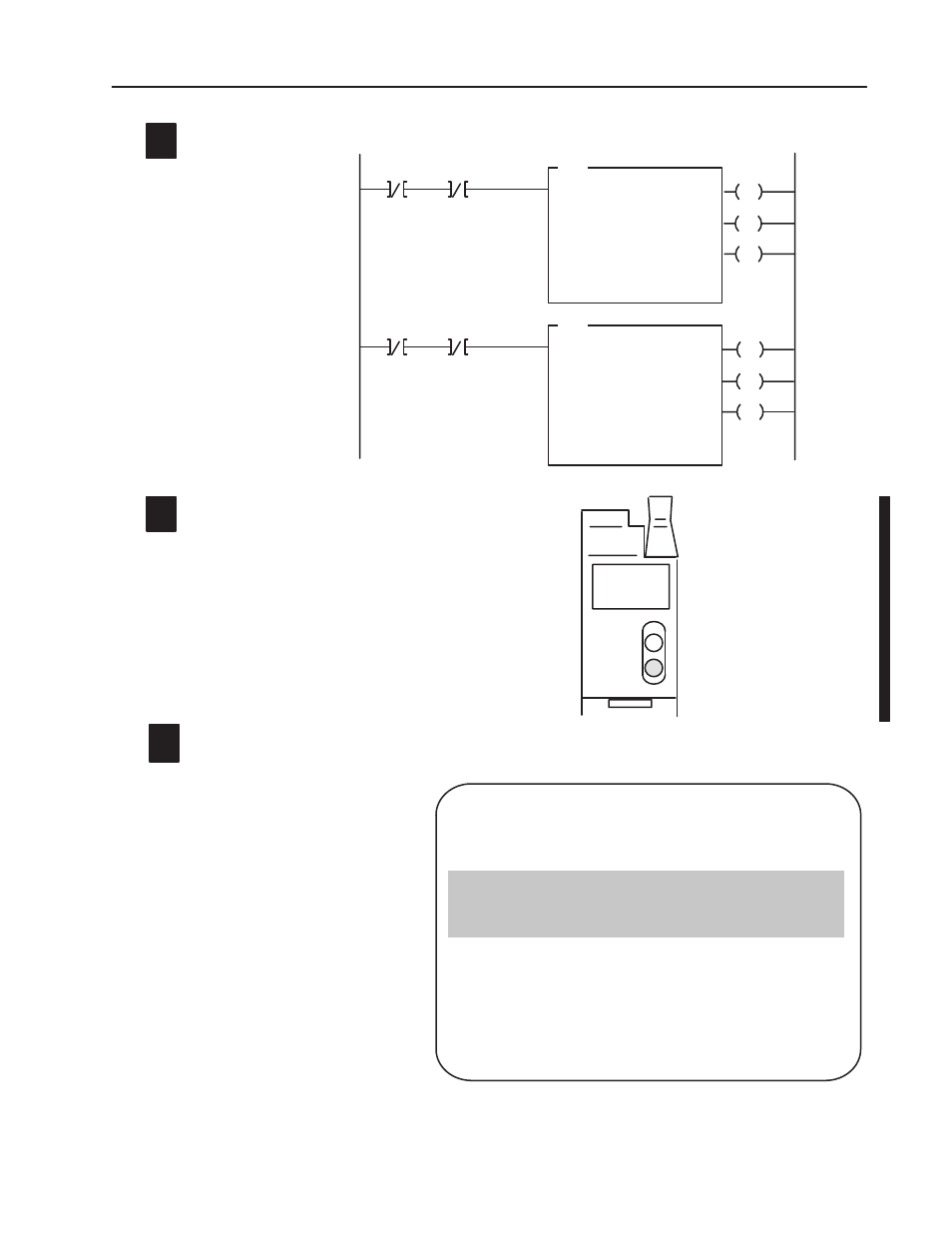
Enter the following ladder logic into the processor.
Note: This programming is only to test
the block transfer write and read functions.
It is not intended for regular use.
RUN
FLT
ANALOG
IN
(12 BIT)
The module lights the green RUNindicator when operating
without fault, or lights the red FAULT indicator when it detects
fault conditions.
4
If the module is operating correctly, the module
will be receiving BTRs and sending BTWs. The
indicator light will indicate green/flashing green.
If the indicator is blinking green, the module
has not received a configuration block transfer
write.
Data Table Report
PLCĆ5/11
Addr 4 IFE
Data Table File N7:0
ADDRESS
N7:10
N7:0
N7:30
N7:20
0
0
0
0
0
0 16533
0 16533
0
0
1
2
3
4
5
6
7
8
9
N7:50
N7:40
N7:70
N7:60
N7:90
N7:80
N7:100
16533
0 16533
0 16533
0 16533
0 16533
0
16533
0 16533
0 16533
0 16533
0 16533
0
16533
0 16533
0 16533
0 16533
0
0
0
2
-1
0
0
0
0
0
0
0
0
0
0
0
0
0
0
0
0
0
0
0
0
0
0
0
0
0
0
0
0
0
0
0
0
0
0
0
0
0
0
0
0
0
0
0
0
0
0
0
0
0
0
0
0
0
0
0
0
0
0
0
0
0
0
0
0
0
0
0
0
This configuration sets the IFE module for:
5
Note: 16533
10
= 4095
16
(BCD)
Block Transfer Write
1Ć5V range
SingleĆended inputs
BCD data format
No digital filter
No real time sampling
0-4095 scaling
Write block transfer
configuration data
Read block
transfer data
Monitor the status bits in word 1 of the
BTR file when troubleshooting your
module.
Note: If all input terminals are shorted together and tied to module common, the input data for all channels will read zero.