Rockwell Automation 1771-IFE ANALOG INPUT MODULE User Manual
Page 24
2–12
Installing the Input Module
Publication 1771Ć6.5.115 - February 1999
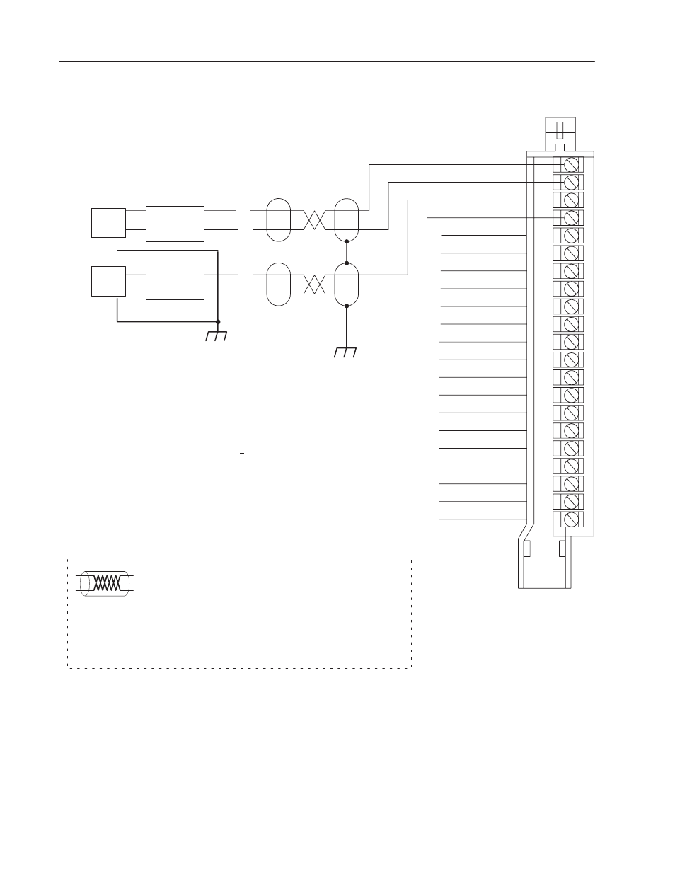
Figure 2.4
Connection Diagram for 8 Differential Inputs and FourĆWire Transmitters
Channel 1+
Channel 1Ć
Channel 2+
Channel 2Ć
Channel 3+
Channel 3Ć
Channel 4+
Channel 4Ć
Channel 5+
Channel 5Ć
Channel 6+
Channel 6Ć
Channel 7+
Channel 7Ć
Channel 8+
Channel 8Ć
Module Common
Not used
Not used
Not used
Module Common
Source Ground
1
. Unused channels must have their + and Ć inputs jumpered
together and tied to module common to reduce noise.
1771ĆWG
Field Wiring Arm
1
2
3
4
5
6
7
8
9
10
11
12
13
14
15
16
17
18
19
20
21
10949-I
Attention: Analog input signals must be within +14.25Vreferenced to module common. If
an input channel exceeds this range, channelĆtoĆchannel crosstalk can cause invalid input
readings and invalid underrange or overrange bits.
NOTE:
The 1771ĆIFE module does not supply loop power for the input device. The user must
supply loop power for loopĆpowered input devices.
+
-
Configuring the module for differential inputs does not provide isolation.
The sensor cable must be shielded. The shield must:
•
extend the length of the cable, but be connected only at the 1771
I/O chassis
•
extend up to the point of termination
Important: The shield should extend to the termination point,
exposing just enough cable to adequately terminate the
inner conductors. Use heat shrink or another suitable
insulation where the wire exits the cable jacket.
+
-
Power
Supply
4ĆWire
Transmitter
Power
Supply
4ĆWire
Transmitter
2
Tie power supply grounds together to
minimize ground loops.
Note: Refer to transmitter manufacturers
specifications for power supply connections.
2