Input range selection – Rockwell Automation 1771-IFE ANALOG INPUT MODULE User Manual
Page 34
4–2
Configuring Your Module
Publication 1771Ć6.5.115 - February 1999
During normal operation the processor transfers 1 to 39 words to the
module when you program a block transfer write instruction to the
module’s address. This BTW file contains configuration words, and
calibration words (words 38 and 39) for each channel.
When a block transfer transfer length of 0 is programmed, the
1771-IFE/C will respond with the series A default length of 37.
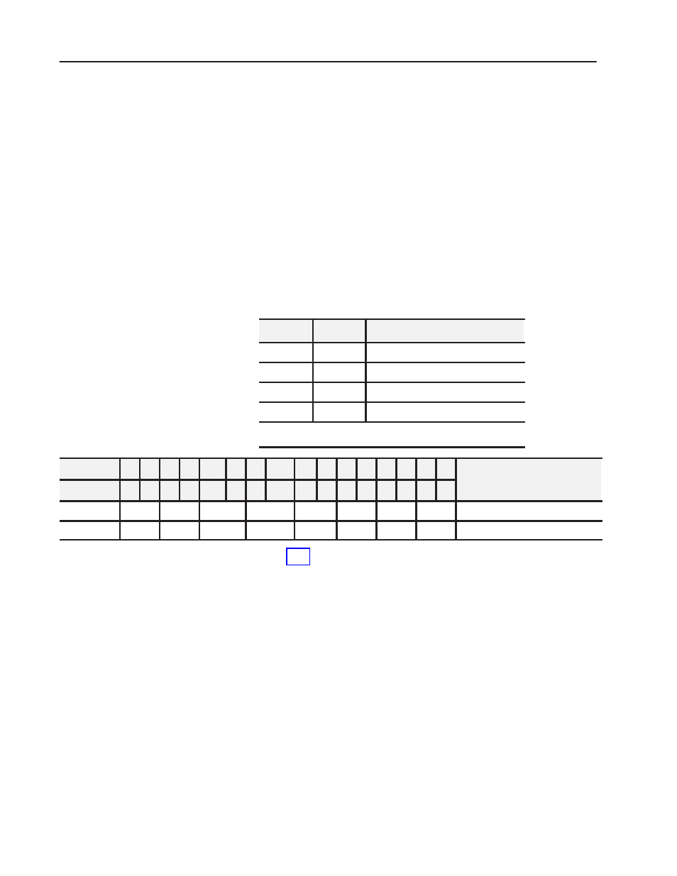
You can configure the module to operate with any of five voltage or
three current ranges. You select individual channel ranges using the
designated words of the block transfer write instruction (Table 4.A).
Use BTW word 1 for range selection of channels 1 through 8, and
BTW word 2 for channels 9 through 16. Two bits are allocated for
each channel.
Table 4.A Input Range Selection Bits
Bit 01
Bit 00
Voltage or current input
0
0
1 to 5V dc, 4 to 20mA
1
0
1
0 to 5V dc, 0 to 20mA
1
1
0
Ć5 to +5V dc, Ć20 to +20mA
1,2
1
1
Ć10 to +10V dc
2
, 0 to 10V dc
1
Current input mode selected by configuration plug.
2
Configurable using biĆpolar scaling.
Dec. Bits
15 14 13 12
11
10 09
08
07 06 05 04 03 02 01 00
Description
Octal Bits
17 16 15 14
13
12 11
10
07 06 05 04 03 02 01 00
Description
Write Word 1
8
7
6
5
4
3
2
1
Range Selection Ć Channels 1 thru 8
Write Word 2
16
15
14
13
12
11
10
9
Range Selection Ć Channels 9 thru 16
Table 4.B shows the incremented voltage or current assigned to each
bit for the seven different input ranges. For example, if the channel
1 input range is 0 to +5V and the actual incoming signal is at
mid-range (+2.5V) the value in the module’s data word would be
0000 1000 0000 0000 (binary) or 2048 (decimal). The input is
2048/4096, or 1/2 of full scale.
Input Range Selection