Installing the analog module – Rockwell Automation 1771-IFE ANALOG INPUT MODULE User Manual
Page 19
2–7
Installing the Input Module
Publication 1771Ć6.5.115 - February 1999
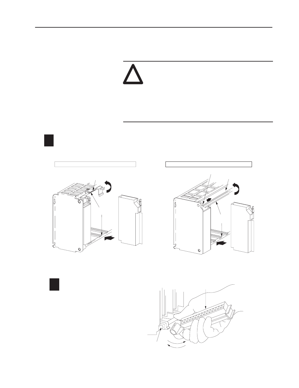
To install your module in an I/O chassis:
1. First, turn off power to the I/O chassis:
!
ATTENTION: Remove power from the 1771 I/O
chassis backplane and field wiring arm before
removing or installing an I/O module.
•
Failure to remove power from the backplane or wir-
ing arm could cause module damage, degradation of
performance, or injury.
•
Failure to remove power from the backplane could
cause injury or equipment damage due to possible
unexpected operation.
Place the module in the card guides on the top and bottom of the slot that guide the
1771ĆIFE/C module into position.
Important: Apply firm even pressure on the module to seat it into its backplane connector.
Swing the chassis locking bar down into place to secure
the modules. Make sure the locking pins engage.
1771ĆA1B, ĆA2B, ĆA3B, ĆA3B1, ĆA4B I/O chassis
1771ĆA1B, ĆA2B, ĆA3B1, ĆA4B Series B I/O chassis
locking tab
card guides
IFE module
IFE module
19809
card guides
locking bar
locking bar pin
Snap the chassis latch over
the top of the module to secure it.
2
17643
wiring arm
install
remove
horizontal bar
Attach the wiring arm (1771ĆWG) to the horizontal
bar at the bottom of the I/O chassis.
The wiring arm pivots upward and connects with
the module so you can install or remove the
module without disconnecting the wires.
1771ĆWG
13
Installing the Analog
Module