Digital filtering – Rockwell Automation 1771-IFE ANALOG INPUT MODULE User Manual
Page 36
4–4
Configuring Your Module
Publication 1771Ć6.5.115 - February 1999
The module has hardware-based high frequency filters on all
channels to reduce the effect of electrical noise on the input signal.
Software digital filtering is meant to reduce the effect of process
noise on the input signal. Digital filtering is selected using BTW
word 3, bits 00-07.
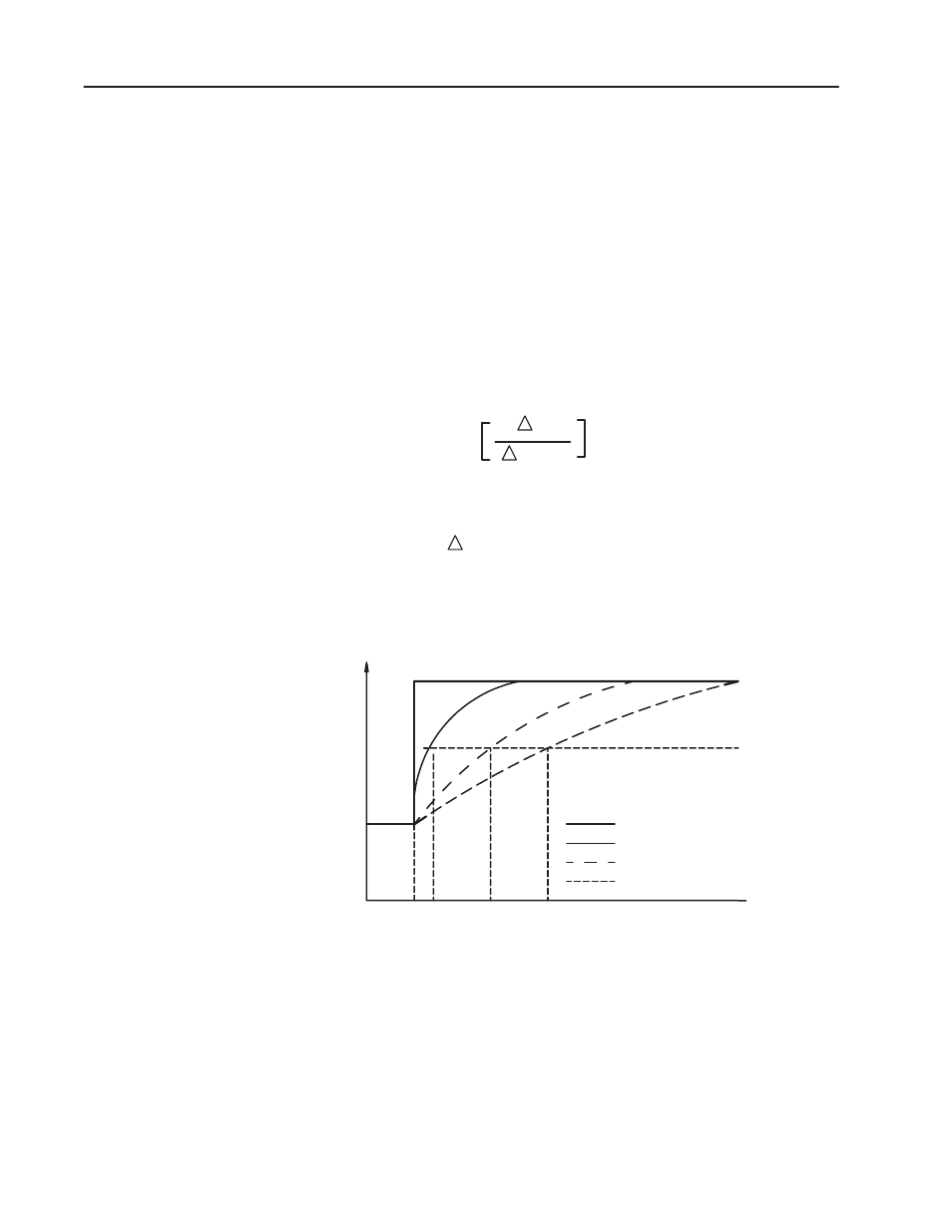
The digital filter equation is a classic first order lag equation
(Figure 4.1). Using a step input change to illustrate the filter
response (Figure 4.2), you can see that when the digital filter
constant time elapses, 63.2% of the total response is reached. Each
additional time constant achieves 63.2% of the remaining response.
Figure 4.1
Digital Filter Equation
Y
n
= Y
n-1
+
t
t + TA
(X
n
- Y
n-1
)
Where: Yn = present output, filtered peak voltage (PV)
Yn -1 = previous output, filtered PV
t = module channel update time (seconds)
X n = present input, unfiltered PV
TA = digital filter time constant (seconds)
Figure 4.2
Digital Filter Lag Equation Illustration
100%
63%
0 0.01
0.5
0.99
Time in Seconds
16723
TA = 0.99 sec
TA = 0.5 sec
TA = 0.01 sec
Unfiltered Input
0
Amplitude
Digital filter time constant values of 0.00 BCD to 0.99 BCD (0.00
BCD = no filter; 0.99 BCD = maximum filter) are set in bits 00
through 07 of word 3 of the block transfer write instruction. If an
invalid digital filter value is entered (i.e., 0.1F), bit 02, word 1 of the
block transfer read instruction will be set. If an invalid digital filter
value is entered, the module will not perform digital filtering. If you
use the digital filtering feature, the filter time constant value chosen
will apply to all input signals.
Digital Filtering