Before you install your input module, Electrostatic damage, Power requirements – Rockwell Automation 1771-IFE ANALOG INPUT MODULE User Manual
Page 14
2–2
Installing the Input Module
Publication 1771Ć6.5.115 - February 1999
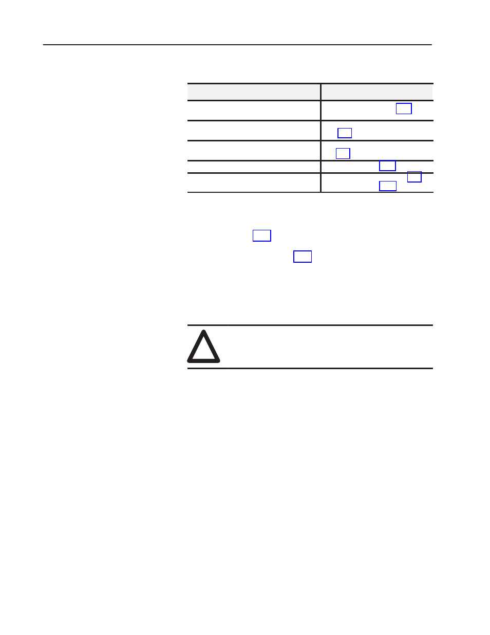
Before installing your input module in the I/O chassis:
You need to:
As described under:
Calculate the power requirements of all
modules in each chassis.
Power Requirements, page 2-2.
Determine where to place the module in the I/O
chassis.
Module Location in the I/O Chassis,
page 2-3.
Set the Series A/B simulation jumper.
Setting the A/B Simulation Jumper,
Key the backplane connector in the I/O chassis. Module Keying, page 2-6.
Make connections to the wiring arm.
Wiring Your Input Module, page 2-8
and Grounding, page 2-13.
Important: The 1771-IFE module is shipped from the factory set
for voltage mode and Series C applications. Refer to
“Setting the Configuration Plugs on the Module”on
page 2–3 for other combinations of current and
voltage inputs and “Setting the Series A/B Simulation
Jumper” on page 2–5.
Electrostatic discharge can damage semiconductor devices inside this
module if you touch backplane connector pins. Guard against
electrostatic damage by observing the following precautions:
!
ATTENTION: Electrostatic discharge can degrade
performance or cause permanent damage. Handle the
module as stated below.
•
Wear an approved wrist strap grounding device, or touch a
grounded object to rid yourself of electrostatic charge before
handling the module.
•
Handle the module from the front, away from the backplane
connector. Do not touch backplane connector pins.
•
Keep the module in its static-shield bag when not in use.
Your module receives its power through the 1771 I/O power supply.
The module requires 500mA from the backplane.
Add this current to the requirements of all other modules in the I/O
chassis to prevent overloading the chassis backplane and/or
backplane power supply.
Before You Install Your
Input Module
Electrostatic Damage
Power Requirements