Rockwell Automation 1771-IFE ANALOG INPUT MODULE User Manual
Page 21
2–9
Installing the Input Module
Publication 1771Ć6.5.115 - February 1999
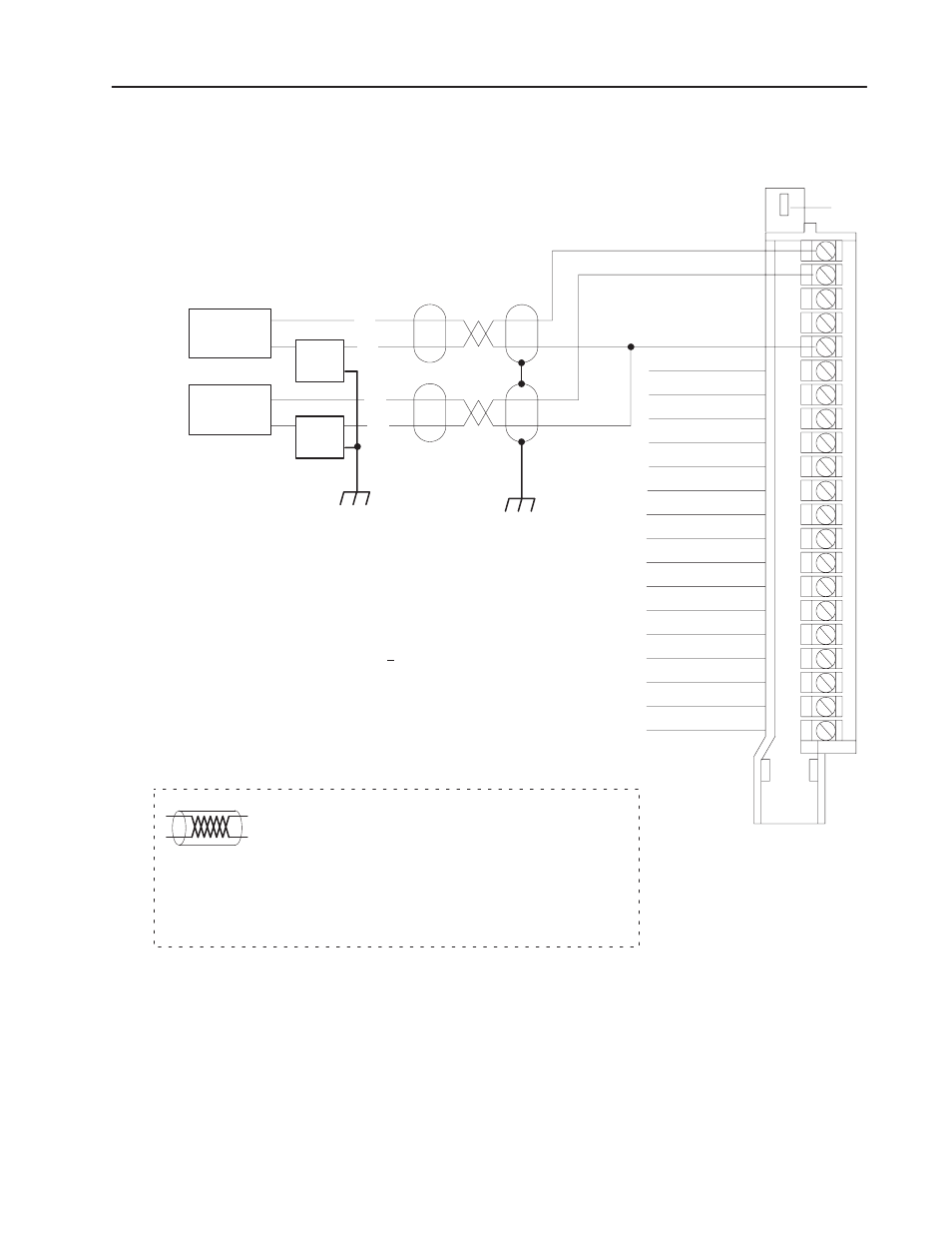
Figure 2.1
Connection Diagram for 16 SingleĆended Inputs and
TwoĆWire Transmitters
3
1
All commons are electrically tied
together inside the module.
2
Jumper all unused channels to
module common to reduce noise.
Source Ground
Channel 1
Channel 2
2
Channel 3
Channel 4
Channel 5
Channel 6
Channel 7
Channel 8
Channel 9
Channel 10
Channel 11
Channel 12
Channel 13
Channel 14
Channel 15
Channel 16
1
Module Common
1
Module Common
1
Module Common
1
Module Common
1
Module Common
1771ĆWG
Field Wiring Arm
1
2
3
4
5
6
7
8
9
10
11
12
13
14
15
16
17
18
19
20
21
10948ĆI
Attention: Analog input signals must be within +14.25Vreferenced to module
common. This input signal includes any common mode voltage present between
either input terminal and module common. If an input terminal exceeds this range,
channelĆtoĆchannel crosstalk can cause invalid input readings and invalid
underrange or overrange bits.
The 1771ĆIFE module does not supply loop power for the input device. The user
must supply loop power for loopĆpowered input devices.
+
-
2ĆWire
Transmitter
The sensor cable must be shielded. The shield must:
•
extend the length of the cable, but be connected only at the 1771
I/O chassis
•
extend up to the point of termination
Important: The shield should extend to the termination point,
exposing just enough cable to adequately terminate the
inner conductors. Use heat shrink or another suitable
insulation where the wire exits the cable jacket.
Power
Supply
+
_
3
Tie power supply grounds together to
minimize ground loops.
Note: Refer to transmitter manufacturers
specifications for power supply connections.
2ĆWire
Transmitter
Power
Supply