Rockwell Automation 1771-IFE ANALOG INPUT MODULE User Manual
Page 41
4–9
Configuring Your Module
Publication 1771Ć6.5.115 - February 1999
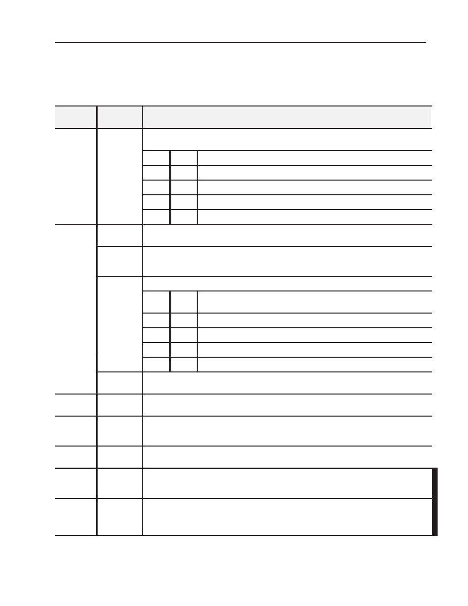
Bit/Word Descriptions for the Analog Input Module BlockTransfer
Write Configuration Block
Note that decimal bits are shown, with octal bits in parentheses.
Word
Decimal Bit
(Octal Bit)
Description
Words 1 and
2
Bits 00Ć15
(00Ć17)
Input range selections allow the user to configure the inputs for any of 7 input voltage or current ranges. Two
bits are required for each channel. Bits 00 and 01 for channel 1, bits 02 and 03 for channel 2, etc.
Bit 01
Bit 00
Voltage or Current Input
0
0
1 to 5V dc, 4 to 20mA (default)
0
1
0 to 5V dc, 0 to 20mA
1
0
Ć5 to +5V dc, Ć20 to +20mA
1
1
Ć10 to +10V dc, 0 to 10V dc
Word 3
Bits 00Ć07
(00Ć07)
Digital filter reduces effect of noise on input. See "Digital Filtering" on page 4-4. (Default is no filter.)
Bit 08
(10)
Input type, set bit for differential mode on all channels.
Reset (0) = singleĆended inputs (default)
Set (1)
= differential inputs
Bits 09Ć10
(11Ć12)
Data format - set to match your processor.
(11Ć12)
Bit 10
(12)
Bit 09
(11)
Data Format
0
0
BCD (default)
0
1
Reserved
1
0
Two's complement binary
1
1
Signed magnitude binary
Bits 11Ć15
(13Ć17)
Real time sampling - Default is no RTS. See appendix A for timing details. See Table 4.E for real time intervals.
Word 4
Bits 00Ć15
(00Ć17)
Minimum sign bits, when set, designate negative minimum scaling values for the corresponding input
channels. Bit 00 corresponds to channel 1, bit 01 corresponds to channel 2, etc.
Word 5
Bits 00Ć15
(00Ć17)
Maximum sign bits, when set, designate maximum scaling values that are negative. Maximum scaling value
must be greater than minimum on any particular channel. Bit 00 corresponds to channel 1, bit 01 corresponds to
channel 2, etc.
Words 6 thru
37
Bits 00Ć15
(00Ć17)
Minimum and maximum scaling values for each channel. Enter in BCD format.
Word 38
Bits 00Ć15
(00Ć17)
Offset calibration - Each bit represents a channel (bit 00 to channel 1, bit 01 to channel 2, etc.). When the bit is
set, and a BTW has been sent, the module will read the channels and adjust the offset to analog ground
potential. In differential mode, bits 08 thru 15 (10 thru 17 in octal) are ignored. In current mode, apply 0mA.
Word 39
Bits 00Ć15
(00Ć17)
Gain calibration - Each bit represents a channel (bit 00 to channel 1, bit 01 to channel 2, etc). When the bit is
set, and a BTW has been sent, the module will read the channels and adjust the gain correction values. If used
on +, 0 to 5, or 1 to 5V ranges, a value of 5V is expected. If used on +10V range, 10V is expected. In differential
mode, bits 08 thru 15 (10 thru 17 in octal) are ignored. In current mode, apply 20mA.