Rockwell Automation 1794-IF4I, -OF4I, IF2XOF2I, -IF4IXT, -IF4ICFXT, -OF4IXT, IF2XOF2IXT FLEX I/O Isolated Analog Modules User Manual
Page 13
Publication 1794-6.5.8 - January 2010
Overview of FLEX I/O and your Analog Modules 13
How FLEX I/O Analog
Modules Communicate
with Programmable
Controllers
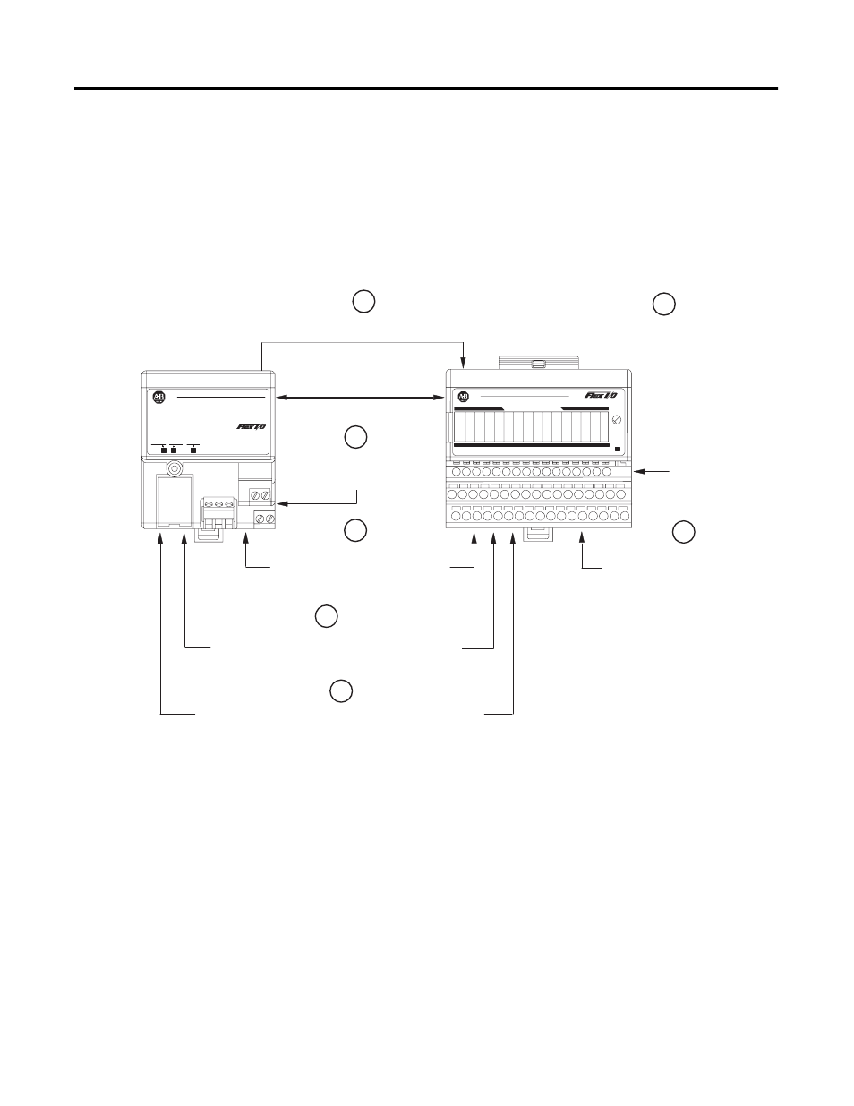
The adapter/power supply transfers data to the module (block transfer
write) and from the module (block transfer read) using BTW and BTR
instructions in your ladder diagram program. These instructions let the
adapter obtain input values and status from the module, and let you
send output values and establish the module’s mode of operation.
Figure 1.2 describes the communication process.
Figure 1.2
An Example of Communication Between an Adapter and an Analog Input Module
ADAPTER
ACTIVE
FAULT
LOCAL
FAULT
24VDC
POWER SUPPLY
RIO ADAPTER
1794-ASB
Allen-Bradley
2
Allen-Bradley
INPUT 0
INPUT 2
INPUT 4
INPUT 6
INPUT 1
INPUT 3
INPUT 5
INPUT 7
I
V I
V
I
V
I
V
I
V
I
V
I
V
I
V
ANALOG INPUT
1794±IE8
1
The adapter transfers your configuration data
to the module using a BTW.
Flexbus
External devices transmit
analog signals to the module.
2
The module converts analog signals
into integer format and stores these
values until the adapter requests their
transfer.
3
Your ladder program instructs the
adapter to perform a BTR of the values
and stores them in a data table.
4
The adapter and module determine
that the transfer was made without error
and input values are within specified
range.
5
Your ladder program can use and/or move the data (if valid)
before it is written over by the transfer of new data in a
subsequent transfer.
6
Your ladder program performs BTWs to the module when you power
it up, and any time you wish to reconfigure the module.
7