Polled i/o structure – Rockwell Automation 1794-IF4I, -OF4I, IF2XOF2I, -IF4IXT, -IF4ICFXT, -OF4IXT, IF2XOF2IXT FLEX I/O Isolated Analog Modules User Manual
Page 100
Publication 1794-6.5.8 - January 2010
100 Input, Output, Status and Configuration Files for Analog Modules when used with ControlNet
The I/O map for a module is divided into read words and write
words. Read words consist of input and status words, and write words
consist of output and configuration words. The number of read words
or write words can be 0 or more. The length of each I/O module’s
read words and write words vary in size depending on module
complexity. Each I/O module will support at least 1 input word or 1
output word. Status and configuration are optional, depending on the
module.
For example, a 16 point discrete input module will have up to 2 read
words and 1 write word.
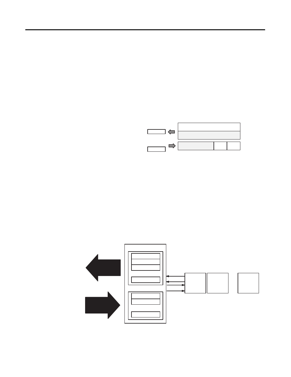
Polled I/O Structure
Output data is received by the adapter in the order of the installed I/O
modules. The Output data for Slot 0 is received first, followed by the
Output data for Slot 1, and so on up to slot 7.
The first word of input data sent by the adapter is the Adapter Status
Word. This is followed by the input data from each slot, in the order
of the installed I/O modules. The Input data from Slot 0 is first after
the status word, followed by Input data from Slot 2, and so on up to
slot 7.
Module Image
Inputs
Delay
Time
Input Size
Output Size
1 or 2 Words
0 or 1 Word
I/O Image
Not used
16-point Discrete Input Module
Delay
Time
Not used
Adapter Status
Slot 0 Input Data
Slot 1 Input Data
Slot 7 Input Data
Slot 0 Output Data
Slot 1 Output Data
Slot 7 Output Data
Read Data
Write Data
Network READ
Network WRITE
DeviceNet Adapter
Slot 0
I/O Module
Read
Write
Slot 1
I/O Module
Slot 7
I/O Module
...
...
...
...
...