Ladder logic – Rockwell Automation 1746-FIO4V SLC 500 Fast Analog I/O/ User Manual User Manual
Page 51
Publication 1746-UM009B-EN-P - September 2007
Write Ladder Logic 51
Ladder Logic
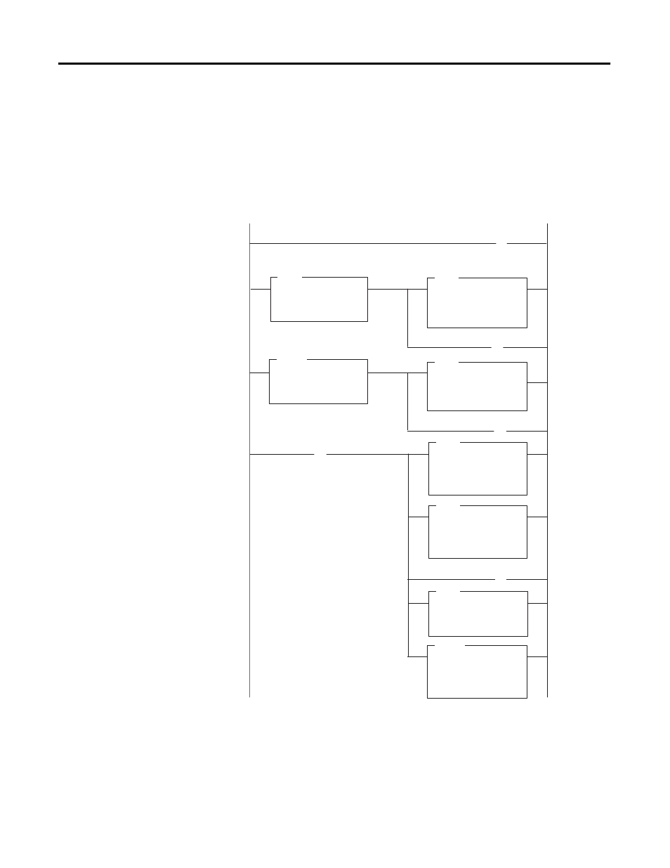
The following ladder logic uses standard math. It unlatches the
mathematical overflow bit S2:5/0 before the end of the scan to
prevent a processor fault. The module is located in slot 2, and the
output device is wired to channel 0.
Scale Offset
] [
GREATER THAN
Source A
Source B
N7:0
100
Rung 2:0
Set in-range bit
Rung 2:1
Check for below range
Rung 2:2
Check for above range
Multiply by the
scaled range
Clear fault bit
from overflow
Add offset
B3/0
(U)
S2:5/0
(U)
LES
GRT
MUL
DDV
ADD
LESS THAN
Source A
Source B
N7:0
0
MULTIPLY
Source A
Source B
Dest
N7:1
3685
N7:1
DOUBLE DIVIDE
Source A
Dest
10
N7:1
ADD
Source A
Source B
Dest
N7:1
205
0:2.0
B3/0
(L)
MOV
MOVE
Source A
Dest
205
0:2.0
B3/0
B3/0
(U)
MOV
MOVE
Source A
Dest
3890
0:2.0
Rung 2:3
Scale the analog input
SUB
SUBTRACT
Source A
Source B
Dest
N7:0
90
N7:1
Subtract the
input minimum.
Divide result
by input range