Address i/o image words – Rockwell Automation 1746-FIO4V SLC 500 Fast Analog I/O/ User Manual User Manual
Page 31
Publication 1746-UM009B-EN-P - September 2007
Processor and Module Considerations 31
Address I/O Image Words
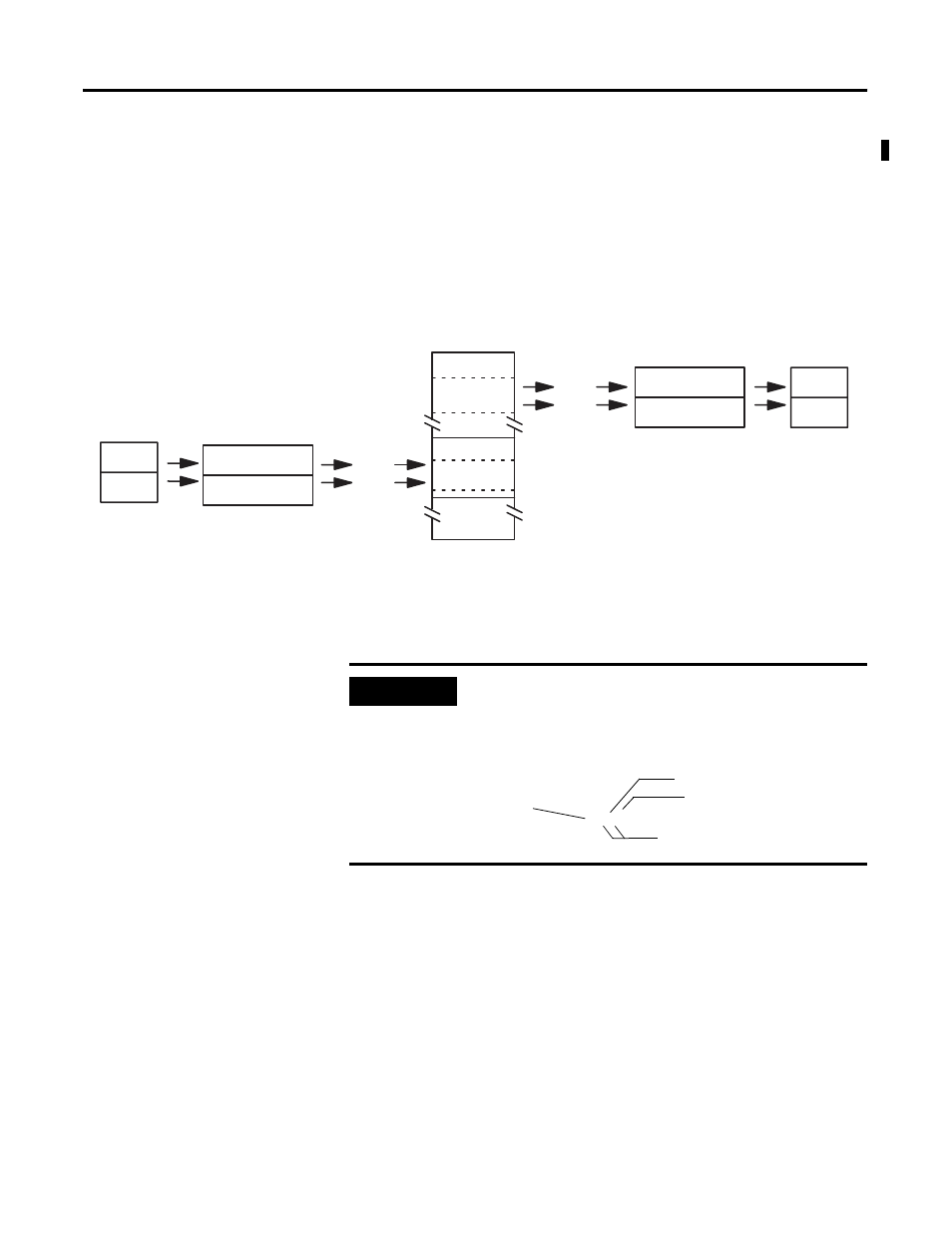
Each module input channel is addressed as a single word in the
processor’s input image table and each module output channel is
addressed as a single word in the processor’s output image table. The
module uses a total of two input words and two output words.
Processor I/O Image Words Used by the Module
The converted input values from input channels 0 and 1 are addressed
as words 0 and 1 of the slot where the module resides. The output
values for the output channels 0 and 1 are addressed as output words
0 and 1 of the slot where the module resides.
Analog Input
Sensors
Word Addresses
in I/O Image File
Input Channel 0
Input Module’s
A/D Converter
Bit 15
Bit 0
Input 0
Input 1
Input Channel 1
Input
Scan
Output Image
Input Image
I:e.0
I:e.1
O:e.0
O:e.1
e = module’s slot number in I/O rack
Output
Scan
Output Channel 0
Bit 15
Bit 0
Output Channel 1
Analog Output
Devices
Output 0
Output 1
EXAMPLE
You would address the output image word for output O, word 0,
in slot 3 as: O:3.0 where delimiters : and . must be placed as
shown.
O:e.0-4
delimiters
Capital Letter
I = Input, or
O = Output
module’s I/O rack slot location
I/O image table word