Rockwell Automation 1746-FIO4V SLC 500 Fast Analog I/O/ User Manual User Manual
Page 19
Publication 1746-UM009B-EN-P - September 2007
Install and Wire the Modules 19
3. Apply shrink wrap where wires leave the casing with the hot-air
blower.
4. Cut off the drain wire and foil shield at the other end of the
cable.
5. Apply shrink wrap to the junction where wires leave the casing.
6. Trim the signal wires to 5 cm (2 in.) lengths. Strip about
4.76 mm (3/16 in.) of insulation away to expose the copper
strands for your connections.
7. Decide where you will connect the cable to earth ground, and
ground it.
Refer to Ground the Cable on page 17.
8. Connect signal wires (black and clear) to the terminal block and
to the input or output device.
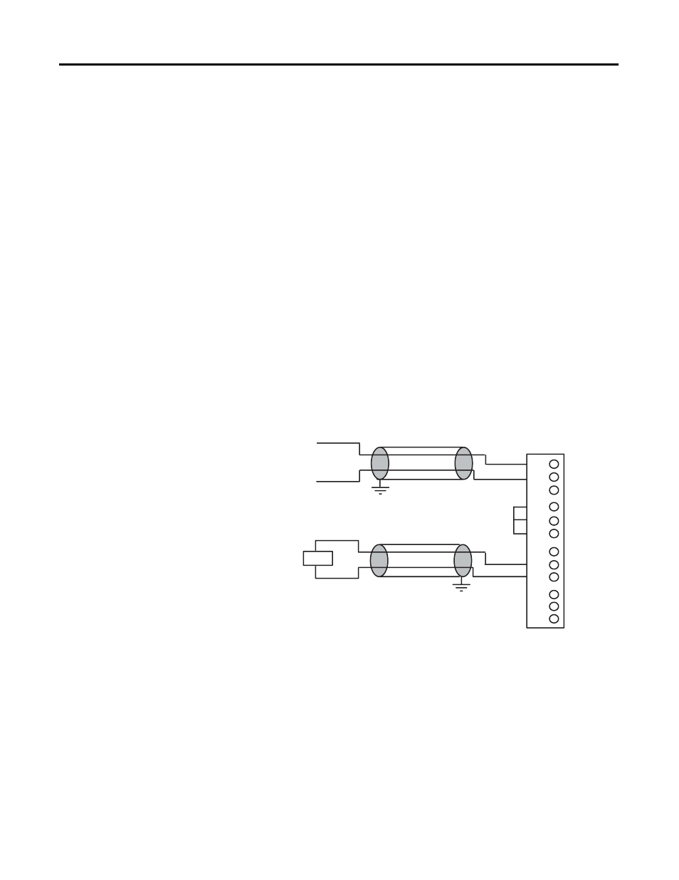
Wiring Diagram for Module, Sensor, and Load (showing differential inputs)
Important: Channels are not isolated from each other.
All analog commons are connected together internally.
Important: Jumper
unused inputs.
Important: Do not
jumper unused outputs.
Load
Analog
Sensor
Earth
Ground
Earth
Ground
+
–
0
1
2
IN 0 +
IN 0 –
ANL COM
3
4
5
IN 1 +
IN 1 –
ANL COM
6
7
8
not used
OUT 0
ANL COM
9
10
11
not used
OUT 1
ANL COM