Overview of scaling inputs and outputs – Rockwell Automation 1746-FIO4V SLC 500 Fast Analog I/O/ User Manual User Manual
Page 42
Publication 1746-UM009B-EN-P - September 2007
42 Write Ladder Logic
We present an alternative program for SLC 5/02 (and later) processors.
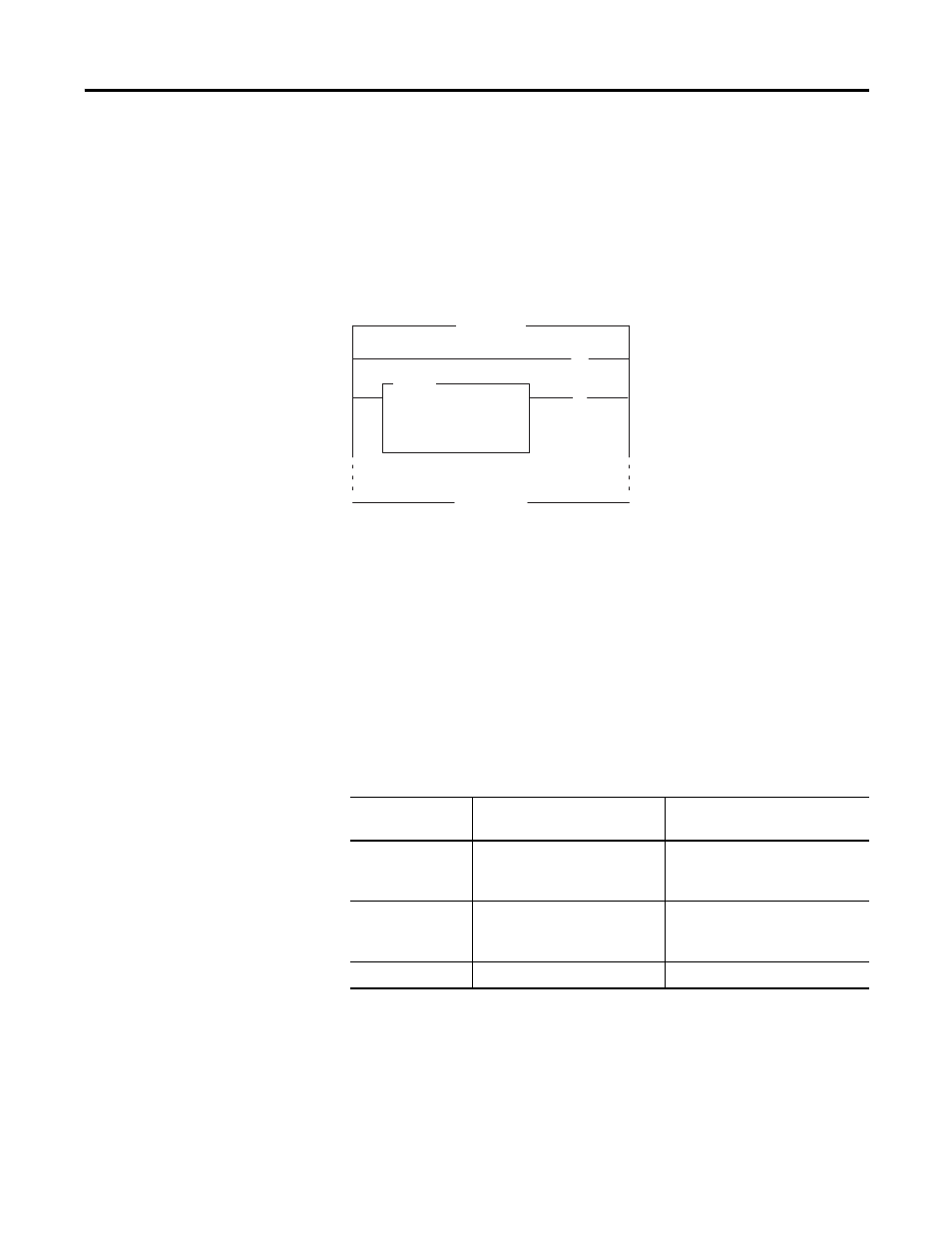
It uses a single Limit Test instruction that checks low and high limits.
Whenever the input value exceeds a limit, this program latches a bit
that could trigger an alarm elsewhere in your ladder program. In this
example, the input range is 0…10V dc (decimal range of 0…4095). If
the input range were 4…20 mA, the low and high limits would be
2047 and 408, respectively.
In both examples, the analog input value is in word 0 of slot 1 (I:1.0).
Overview of Scaling Inputs
and Outputs
Scaling is the application of a ratio on the variable to be scaled, where
the ratio is the scaled range (
Δy) to the input range (Δx).
The purpose for scaling values when programming analog I/O
modules is to change data format.
MAIN
Turn OFF Alarm
Turn ON Alarm,
Limit Exceeded
LIM
END
LIMIT TEST (CIRC)
Low Lim
Test
High Lim
4095
I:1.0
408
B3/0
(U)
B3/0
(L)
Remainder of Program
Scaling Inputs and Outputs
When you scale
You start with this data
format
And typically change the
format to
Inputs
Decimal input range in raw
counts (from the module’s A/D
converter)
Engineering units such as PSI
(stored in the data table)
Outputs
Integer values from the data
table (or from the input image
table)
Decimal output range in raw
counts to match the module’s
output range
On a linear graph
Δx
Δy