Rockwell Automation 1746-FIO4V SLC 500 Fast Analog I/O/ User Manual User Manual
Page 43
Publication 1746-UM009B-EN-P - September 2007
Write Ladder Logic 43
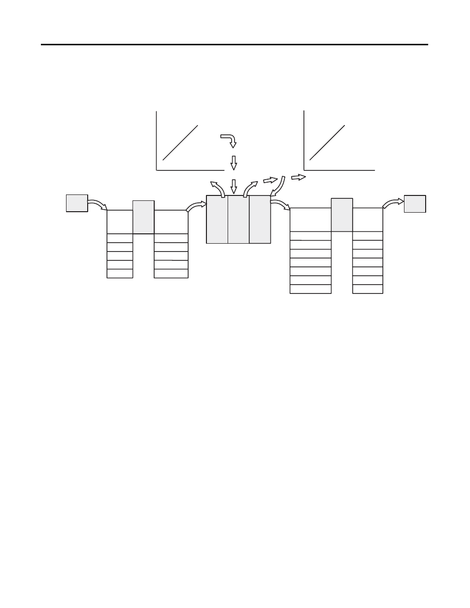
We illustrate input and output scaling, the source and type of data to
be scaled, and the type and destination of the scaled data.
Data Scaling
You scale data with ladder logic using arithmetic instructions such as
add, multiply, and double divide; or by using the scaling instruction
available with SLC 5/02 (or later) processors. The scaling computation
is as follows:
In this context, the input value and input range are inputs to the
scaling function, not necessarily inputs associated with the sensor
input.
Scaled Values
in Engineering
Units for Data
Table (
Δy)
Scaled Values
to Match
Module’s Raw
Counts
Input Scaling
Output Scaling
Module’s Input in
Raw Counts (
Δx)
Integer Values (from Data
Table or Input Image)
Module’s Input in
Raw Counts (
Δx)
Sensor
Module
A/D
Input
Image
Table
Data
Table
Output
Image
Table
Module
D/A
Output
Device
Input
Signal
Range
Input Raw
Counts
from A/D
Output
Signal
Range
Input Raw
Counts to
D/A
0…5V dc
1…5V dc
0…10V dc
0…20 mA
4…20 mA
0…2047
409…2047
0…4095
0…2047
409…2047
0…16,384
3277…16,384
0…32,764
-32,768…32,764
0…31,208
6242…31,208
0…32,764
0…5V dc
1…5V dc
0…10V dc
-10 …10V
0…20 mA
4…20 mA
0…21 mA
Scaled value = (input value x slope) + offset
Slope =
Δy/Δx = scaled range / input range
= (scaled max. – scaled min.) / (input max. – input min.)
Offset = scaled min. – (input min. x slope)