Auxiliary contacts inspection and replacement – Rockwell Automation 1512A MV Controllers - 800A One-High Cabinet User Manual
Page 62
5-14
Maintenance
1512A-UM102B-EN-P – June 2013
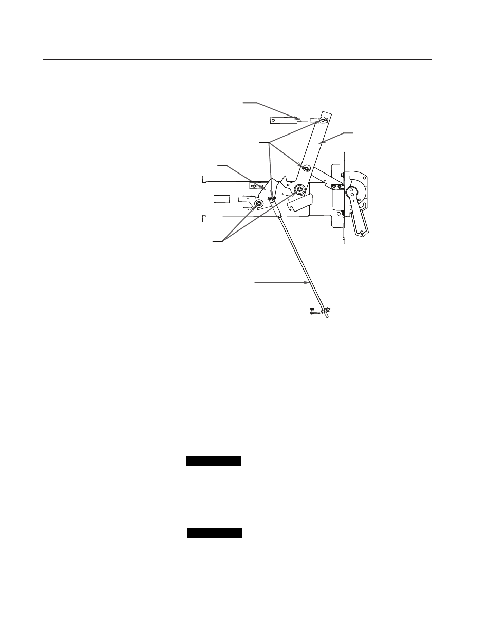
Threaded Connecting Rod
Clevis Pins and Cotter Pins
Switch Interlock Lever
Isolation Switch
Operating Lever
Lubrication Points
(Only at replacement)
Contactor Interlock Rod
Threaded Connecting Rod
Clevis Pins and Cotter Pins
Switch Interlock Lever
Isolation Switch
Operating Lever
Lubrication Points
(Only at replacement)
Contactor Interlock Rod
Figure 5.12 – Isolation Switch Handle Mechanism Lubrication Points
5) Inspect the mounting hardware on the isolation switch operating
lever and contactor interlock rod (see Figure 5.11). Tighten any
loose hardware.
6) Inspect the isolation switch blades and the incoming line stabs (see
Figure 5.12). The mating surfaces must be clean and well lubricated.
7) Remove any dirt and dried grease.
Do not scrape or file the parts. This may remove the
plating and expose the underlying copper to corro-
sion.
8) Lubricate the isolation switch blades and the isolation switch blade
pivot points with Nyogel 759G (see Figure 5.12).
Lubricate the isolation switch blades a minimum of
once per year to avoid excessive wear to the compo-
nents and to prevent the isolation switch blades from
overheating.
Auxiliary Contacts
Inspection and Replacement
I M P O R T A N T
I M P O R T A N T
I M P O R T A N T
I M P O R T A N T
Isolation Switch Mechanism
Inspection and Lubrication
(cont.)