Rockwell Automation 1512A MV Controllers - 800A One-High Cabinet User Manual
Page 60
5-12
Maintenance
1512A-UM102B-EN-P – June 2013
To Reduce the Gap Distance
5) Loosen the two screws in the stop bracket and move the stop
bracket up against the interlock lever.
6) With the feeler gauge positioned in the gap, move the interlock
lever and the stop bracket closer to the isolation switch operating
lever to reduce the gap space. Tighten the stop bracket screws.
7) Tighten the nylock nut until it is snug against the contactor inter-
lock lever. Do not overtighten the nylock nut as it will move the
interlock lever and reduce the gap. Proceed to Step 11.
To Increase the Gap Distance
8) Loosen the two screws in the stop bracket and move the stop
bracket away from the interlock lever.
9) Loosen the nylock nut until the gap reaches the desired size.
10) Move the stop bracket until it just touches the interlock lever and
tighten the screws.
11) Apply Loctite 290 (or equivalent adhesive) to the stop bracket
screws and torque the screws to 6 ft.-lb. (8 N•m).
12) Move the isolation switch handle to the ON position.
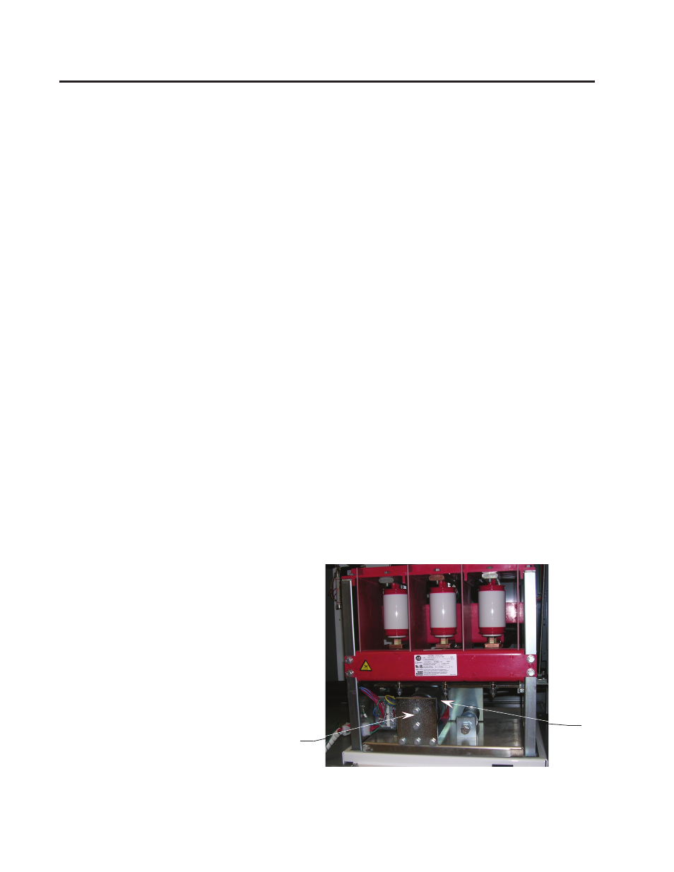
13) Manually close the contactor by attaching locking pliers to the
contactor interlock lever and pushing down until the armature plate
contacts the magnetic cores (see Figure 5.9). Verify that the inter-
lock lever overlaps the isolation switch operating lever by at least
0.125 in. (3 mm) (see Figure 5.10).
Figure 5.10 – Closing Contactor Manually (Some parts not shown)
Contactor Interlock Rod Adjust-
ment - (cont.)