Rockwell Automation 1512A MV Controllers - 800A One-High Cabinet User Manual
Page 31
3-6
Installation – Arc Resistant (ArcShield)
1512A-UM102B-EN-P –June 2013
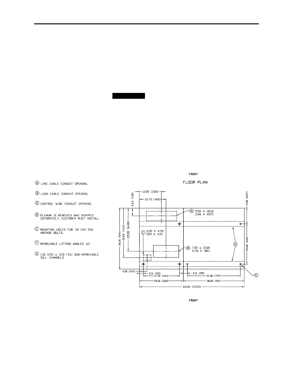
Anchoring
Place the controller in the desired installation location. Use ½ in. (M12) floor
mounting bolts to securely fasten the controller to the mounting surface.
See Figure 3.4 and 3.5 as an example of the location of the mounting holes
in the cabinet.
Note: Refer to Dimension Drawing provided with order
documentation for additional details related to cabinet floor
plan.
Pre-determined cabinets have been designed for
Uniform Building Code (UBC) seismic zone 1, 2A,
2B, 3 and 4, and IBC (International Building Code) seismic activity
without overturning or lateral movement, provided they are securely
mounted according to UBC, IBC and local building codes. This can
include concrete pad design, steel floor design and the sizing of cabinet
anchors. Concrete floor cutouts must not be adjacent to floor anchor
bolts and must be sized to seismic load. Consult factory if floor mounting
must be reviewed by an accredited engineer. Many jurisdictions require
an engineer from the local area to review the design. Seismic qualification
does not indicate that the equipment will function properly after a
seismic event.
Figure 3.4 – Cabinet Floor Plan – Top Entry/Exit Units, Arc Resistant Cabinet
I M P O R T A N T
I M P O R T A N T