Rockwell Automation 1512A MV Controllers - 800A One-High Cabinet User Manual
Page 43
4-4
Common Installation
1512A-UM102B-EN-P – June 2013
A T T E N T I O N
A T T E N T I O N
To avoid shock hazards, lock out incoming power (see
page 5-3) before working on the equipment. Verify
with a hot stick or appropriate voltage measuring
device that all circuits are voltage free. Failure to do so
may result in severe burns, injury or death.
Incoming cables are connected to the power bus in the last section on the
left.
I M P O R T A N T
I M P O R T A N T
For Non-ArcShield units, incoming line cable size
should not exceed 1-750 MCM or 2-500 MCM per
phase.
For ArcShield units, incoming line cable size should
not exceed 1-500 MCM or 2-4/0 per phase.
For larger cables, an incoming line module must be
used for either cabinet styles.
1) Remove the center-back plate or side plate to access the power bus. If
access to the rear of the unit is not possible, refer to Accessing the Power
Bus for either Standard or ArcShield enclosure.
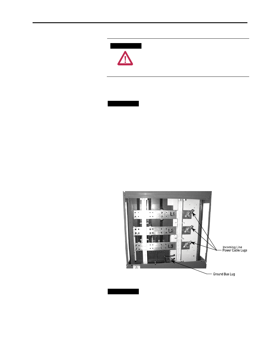
2) Connect the incoming power lines to the power bus. Torque to
specifications (see page 1-3) (Figure 4.4).
Figure 4.4 – Incoming Line Cable Connections, Typical
I M P O R T A N T
I M P O R T A N T
If line cables require installation by front access,
complete the incoming line connection before
installing load cables.
3) Connect the ground wire to the ground bus lug.
Incoming Line Cable
Connections