Rockwell Automation 1512A MV Controllers - 800A One-High Cabinet User Manual
Page 32
Installation – Arc Resistant (ArcShield) 3-7
1512A-UM102E-EN-P – June 2013
Note: Joining hardware can be found in a package mounted to the
front of the shipping skid. Refer to publication MV-QS050_-EN-P for
level floor surface requirements.
1) Remove the side bus access covers if applicable.
2) Position the left side section on a level surface and secure the
section in place with ½ in. (M12) floor mounting bolts (Refer to
Anchoring: ArcShield, page 3-5).
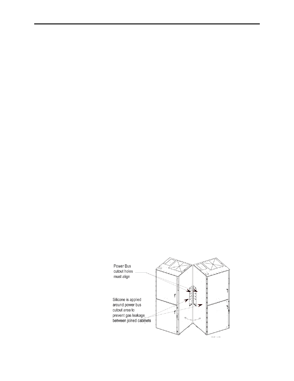
3) When joining ArcShield sections, apply a continuous 1/8-in.-(3-
mm) – wide bead of silicon sealer around the entire outer
perimeter of one section AND around the cutout for the power
bus.
4) Position the right section against the left section. Ensure that the
surface is level.
5) Secure the sections together using the ¼-20 self-tapping screws.
Thread the screw through the 0.281 in. clearance hole to the
corresponding 0.219 in. pilot hole. To access the front clearance
holes of the left-side cabinet, open the medium voltage doors. To
access the rear clearance holes remove the rer covers of the starter.
If rear access is not available, refer to Access to the power Bus –
Front Access, page 3-11.
6) Use the provided ¼-20 thread fasteners to secure the entire
perimeter of the horizontal bus. Ensure there is a continuous bead
of silicone seal around the bus bar opening on one cabinet.
7) Secure the right section to the floor using ½ in. (M12) floor
mounting bolts (refer to Anchoring, page 3-5).
Note: ArcShield units at the end of a line-up have a ground
connection to the outside side bus access cover (see Figures 3.9 and
3.10). This connection must be maintained to ensure unit arc resistant
performance.
Figure 3.5 – Joining Sections
Joining Sections