Rockwell Automation 20G PowerFlex 755 IP00 NEMA/UL Open Drive - Frames 8-10 User Manual
Page 73
Rockwell Automation Publication 750-IN020C-EN-P - May 2012
73
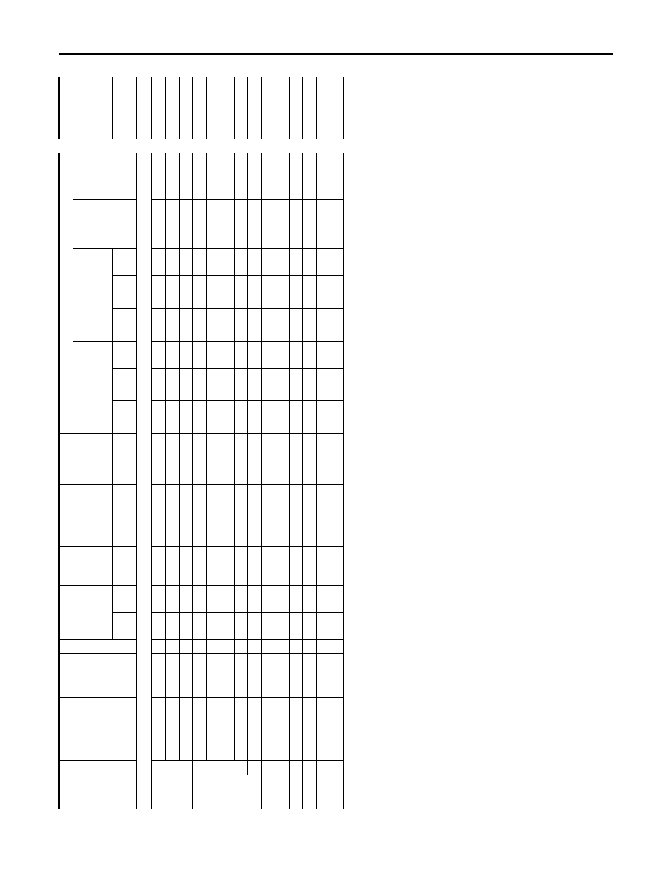
PowerFlex 755 IP00, NEMA/UL Open Type Drive
600 V
olt A
C Inp
u
t (cont
inu
ed
)
810V DC
Inp
u
t
90
0 Hp
9
81
5
Heav
y
20
G11T
E980
2
1223
14
70
76
9
900
10
00
95
0
475
17
00
950
47
5
2300
2300
95
0
100
0
82
5
N
orm
al
20
G11T
E435
2
908
12
60
77
9
900
10
00
95
0
475
18
00
950
47
5
2300
2300
95
0
100
0
83
5
Light
20
G11T
E395
2
919
–
788
900
10
00
1000
500
18
00
100
0
50
0
24
00
2400
10
00
100
0
95
0 Hp
9
90
0
Norm
al
20
G11T
E460
2
990
13
68
84
9
900
10
00
1050
525
19
00
105
0
52
5
25
00
2500
10
50
100
0
90
0
Light
20
G11T
E435
2
990
–
849
900
10
00
1050
525
19
00
105
0
52
5
25
00
2500
10
50
100
0
10
00 Hp
9
98
0
Norm
al
20
G11T
E980
2
1078
14
70
92
5
900
10
00
1150
575
21
00
115
0
57
5
28
00
2800
11
50
100
0
98
0
Light
20
G11T
E460
2
1078
–
925
900
10
00
1150
575
21
00
115
0
57
5
28
00
2800
11
50
100
0
10
92
0
H
eav
y
20
G11T
E395
3
1380
16
65
86
8
900
10
00
1100
550
20
00
110
0
55
0
26
00
2600
11
00
100
0
11
00 Hp
9
10
45
Light
20
G11T
E980
2
1150
–
986
900
10
00
1250
625
22
00
125
0
62
5
30
00
3000
12
50
100
0
10
11
10
Norm
al
20
G11T
E395
3
1221
16
65
1048
900
10
00
1300
650
24
00
130
0
65
0
31
00
3100
31
00
100
0
12
00 Hp
10
12
20
Light
20
G11T
E395
3
1342
14
64
1151
900
10
00
1450
725
26
00
145
0
72
5
35
00
3500
35
00
100
0
12
50 Hp
10
11
90
Heav
y
20
G11T
E510
3
1785
21
45
1123
900
10
00
1400
700
25
00
140
0
70
0
34
00
3400
34
00
100
0
14
00 Hp
10
14
30
Norm
al
20
G11T
E510
3
1573
21
45
1350
900
10
00
1700
850
30
00
170
0
85
0
41
00
4100
41
00
100
0
15
00 Hp
10
15
30
Light
20
G11T
E510
3
1683
18
36
1444
900
10
00
1800
900
32
00
180
0
90
0
43
00
4300
43
00
100
0
(1)
“Ap
plied Ra
ting
”
re
fers t
o the mot
or tha
t wi
ll be connec
te
d to the dri
ve
. F
or exa
m
pl
e,
a “
E4
20
” d
riv
e c
an
b
e u
sed
in
No
rm
al
D
ut
y
m
ode
on a 45
0 Hp mot
or
, i
n
Hea
vy D
ut
y m
ode on a
350 Hp m
ot
or or in Li
ght D
ut
y mod
e on a 5
00 Hp m
ot
or
. T
he dri
ve
ca
n be pr
ogr
ammed for
each mode
. W
iring and fuses
ca
n
be
sized ba
sed
on the pr
ogramme
d mode
. F
or an
y giv
en
dr
iv
e catalo
g
numbe
r, N
ormal D
ut
y mode pr
ov
ides hig
her c
on
tinuous c
urr
en
t bu
t smaller
ov
er
lo
ad c
urr
en
t with r
espec
t t
o Hea
vy
D
ut
y mode.
S
ee
pa
ra
met
er 30
6
[D
ut
y Ra
ting].
Re
fe
r
to
Specific
at
ions for an e
xp
lana
tion of D
ut
y
Ra
tings
.
(2
)
Thes
e A
C li
ne f
use
s (w
ith bl
ow
n f
use
indi
ca
to
rs)
ar
e
inc
lude
d in the
driv
e t
o
pr
ov
ide
driv
e s
hor
t ci
rc
uit pr
ot
ec
tion. A
C i
np
ut pr
ot
ec
tion dev
ic
es for branch c
irc
uit pr
ot
ec
tion based
on U
S
NE
C ar
e list
ed in
the
table
. E
ach driv
e ba
y has one f
use p
er ph
as
e.
(3)
M
inimum pr
ot
ec
tion devic
e siz
e is th
e l
ow
est ra
ted d
evi
ce
that sup
pl
ie
s m
ax
imum p
rot
ec
tion without nuisance trip
ping
.
(4)
M
aximum pr
ot
ec
tion devic
e siz
e is the hi
ghest r
at
ed devic
e tha
t sup
plies
dr
iv
e pr
ot
ec
tion
. F
or U
S N
EC
, mi
nim
um si
ze
is
12
5%
of
motor FL
A. R
ating
s shown are ma
xi
mum
.
(5
)
Circui
t B
rea
ke
r -
in
ve
rse
ti
m
e br
ea
ke
r. F
or U
S NEC, m
ini
mu
m s
iz
e is
1
25%
of
motor FL
A. R
ating
s s
hown are m
axi
m
um.
(6)
Rec
ommended Mot
or cir
cuit p
rot
ec
to
r - Instan
taneous trip cir
cuit br
eak
er
. T
he trip setting
sh
ould
be set t
o the in
pu
t curr
en
t of
the
driv
e and should be sized for the con
tinuo
us c
urr
ent
of
the syst
em
.
(7
)
Thes
e DC
li
ne f
use
s (w
ith bl
ow
n f
use
indi
ca
to
rs)
ar
e
inc
lude
d in the
driv
e t
o
pr
ov
ide
driv
e s
hor
t ci
rc
uit pr
ot
ec
tion.
Ap
pli
ed
Ra
ti
ng
(1
)
Equi
v. F
ram
e
Co
nt
.
Ou
tp
u
t
Amps
D
u
ty
Ca
talo
g
Numb
er
Quan
tit
y
Ou
tp
u
t
O
ver
load Amps
Co
ntinuo
us
AC
In
p
u
t
AC
Input Inte
gral
Semico
ndu
ct
or
Fu
se S
iz
e
(170M
)
(2
)
DC B
ay to
Ba
y
Integra
l
Se
m
ic
on
d
u
ct
or
Fu
se
S
ize
(170M6
648)
AC
Input
Pr
ot
ec
tion De
vices Recommended f
or Br
anch C
irc
uit Pr
ot
ec
tion
D
C Input
Int
egral
Semico
ndu
ct
or
Fu
se
S
ize
(170
M6253
)
(7
)
D
ual E
lement Tim
e Dela
y
Fuse
N
on-
Time
Dela
y F
u
se
Ci
rc
u
it
Break
er
Ma
x S
iz
e
(5
)
Motor
C
irc
ui
t
Prote
ctor
(6
)
1 m
in
3 se
c
Amps
Amps
Am
ps
1/
Ph
as
e
Mi
n
(3)
2/P
has
e
Mi
n
(3)
Ma
x
(4)
1/
Phas
e
Min
(3)
2/
Pha
se
Min
(3)
Max
(4)
Am
ps