Rockwell Automation 161 SERIES A User Manual
Page 18
Bulletin 161
12
Input /
Function
Function
Description
[USP]
13
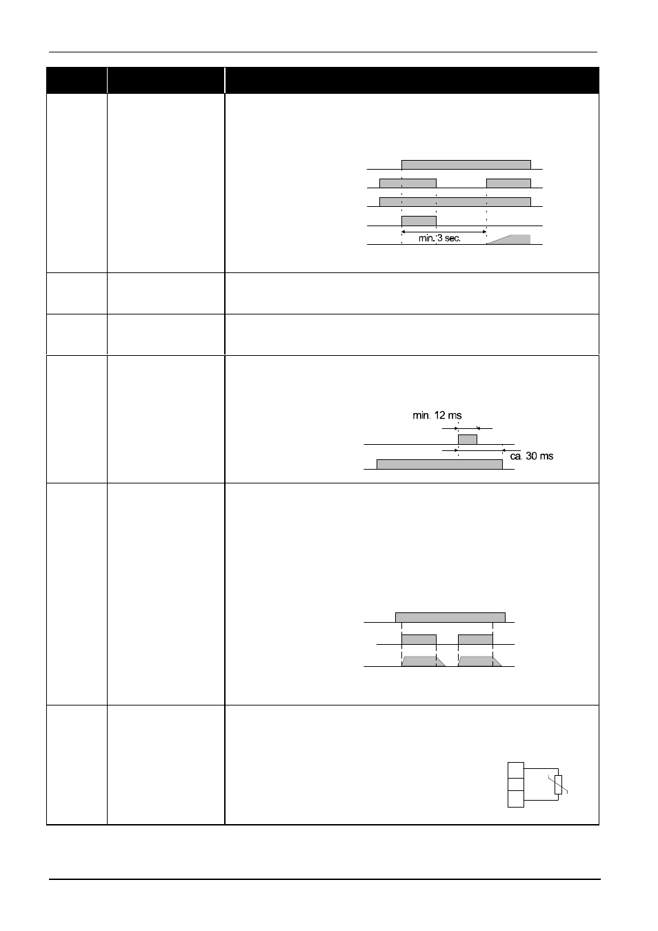
Restart lock
The restart lock prevents a uncontrolled restart of the Bulletin 161 drive
when – after power off – the power supply returns and a start command is
issued immediately or straight afterwards. In this case the following fault
indication will be given:
E13
A new start command or a reset will clear the fault indication.
[SFT]
15
Parameter protection
Parameter protection protects parameters entered from being lost by
overwriting. If the software protection is activated, no data can be lost (see
parameter
b31
).
[AT]
16
Frequency command
input OI active
(4-20 mA)
In the factory default input O (0-10V) is active. Switching to OI is effected
via input [AT]. If there is no digital input programmed as [AT], the
frequency command values are added to O and OI (see parameter
A01
).
[RS]
18
Reset
Clearing a fault indication; reset the fault indication relay. If a reset
command is given during operation, the terminal stages are switched off
and the motor will coast.
[JG]
06
Jog
Jog control is used e.g. to set up a machine manually. This is done via the
inputs [FW] or [RV] if the input [JG] is controlled. When a start command
is given, the frequency programmed under parameter
A38
will be switched
directly to the motor – the start ramp is not active. For the stop command,
three different modes can be selected under parameter
A39
:
1.) The motor will coast
2.) The motor is slowed down at the deceleration ramp
3.) Braking of the motor using the DC brake (see parameter
A54
,
A55
)
Jog control will not be possible if the jog frequency set is less than the start
frequency entered under parameter
b82
.
[PTC]
19
PTC input
Only in connection
with input 5
Reference potential
is terminal L
Input 5 can be programmed as a PTC input under parameter
C05
.
In this case, terminal L will be the reference potential (in all other cases the
reference potential will be at terminal P24).
Output frequency
Start command [FW, RV]
Power supply
Fault indication relay
Input [USP]
Input [RS]
Input [JG]
Fault indication relay
Start command [FW], [RV]
Motor speed
L
5
If the PTC resistance exceeds 3 k
Ω
, the motor
will be switched off and the fault indicator
E35
(ERROR PTC) will be issued.