Rockwell Automation 161 SERIES A User Manual
Page 13
Bulletin 161
7
Terminal
Function
Description
L1, N
Mains connection
1 ~ 200 - 240 V +/- 10%, 50/60 Hz +/- 5%
U/T1
V/T2
W/T3
Motor connection
Star or delta connection of the motor in accordance with the rated
voltage
+
_
DC-bus connection
Connection for brake chopper
+
+1
Connection for DC-bus
reactor
If an DC-bus reactor is connected, remove the copper bridge.
Ensure that the bridge between the terminals + and +1 is installed if
there is no DC-bus reactor installed.
PE conductor connection
Terminal type
MinMax Torque (Nm.)
Power terminals
161S-AA01 / AA02: open terminals, M3.5 screw
0.8 Nm, max. 0.9 Nm
All others: open terminals, M4 screw
1.2 Nm, max. 1.3 Nm
Control terminals
Closed terminals
0.2 Nm, max. 0.25 Nm
Fault indication relay
Closed terminals
0.5 Nm, max. 0.6 Nm
Earth
M4 screw
1.2 Nm, max. 1.3 Nm
Disconnecting or connecting the motor, changing the number of poles in pole-changing motors or changing the
direction of rotation by means of an external device (e.g. contactor) is not permitted during operation.
Connecting capacitive loads is not permitted. A variety of cable types are acceptable for the drive installation.
For many installation,
unshielded
cable is adequate, provided it can be separated from sensitive circuits. If you
cannot separate motor cables from sensitive circuits, or if you must run motor cables from multiple drives (more
than three) in a common conduit or cable tray,
shielded
motor cable is recommended to reduce system noise.
(refer to Appendix A). In the case of motor lead lengths > 50 m, output reactors should be used.
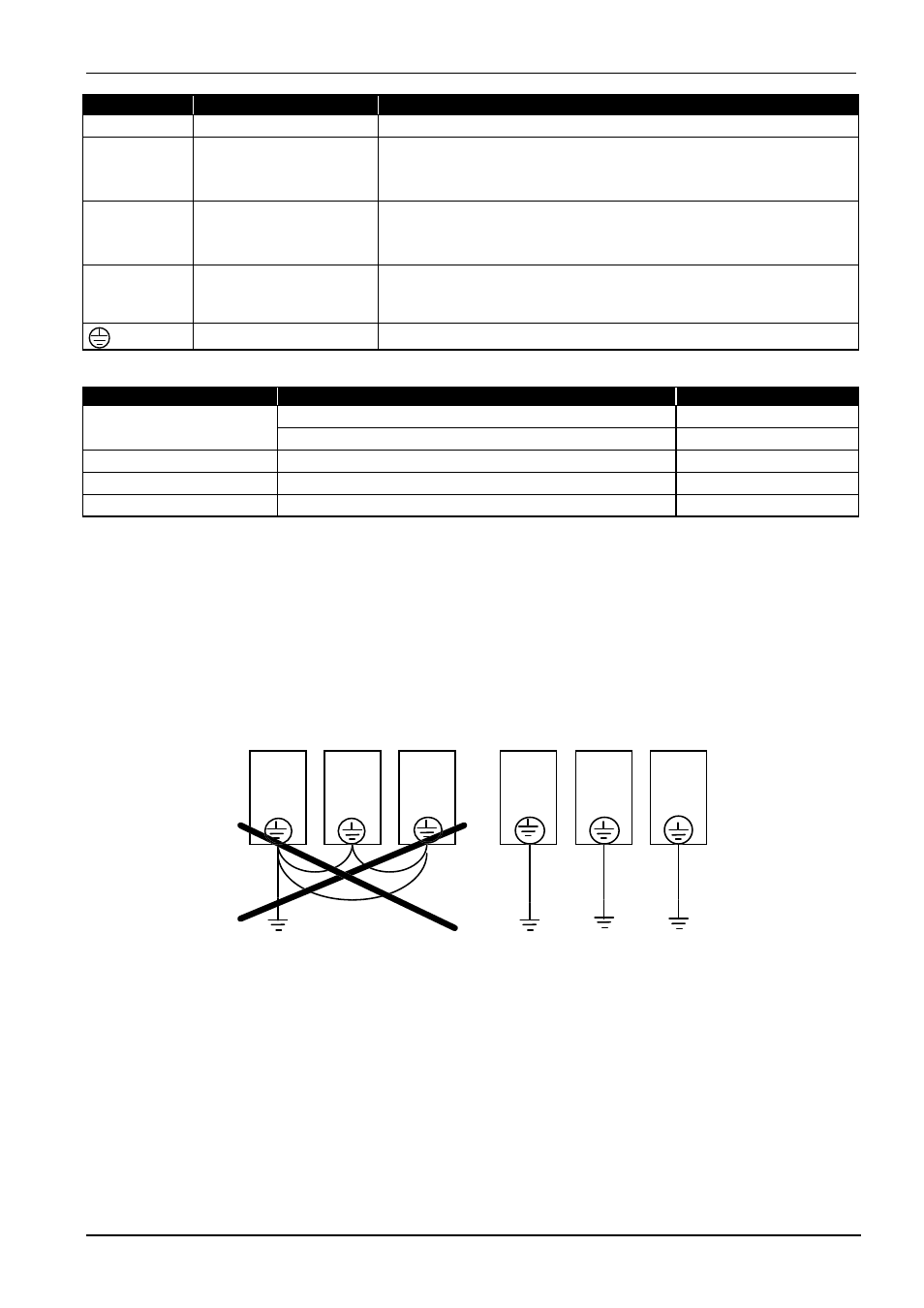
Earth the drive carefully in accordance with the instructions. Avoid the use of shared protective earth
conductors if several Bulletin 161 drives are used.
&
&
&
&
&
&
The power factor cos
φ
of the mains power supply must not exceed 0.99. Compensation systems must be
tested for reliability to ensure that overcompensation does not occur at any time.
Attention! Input line reactors 3% impedance must be installed under the following conditions:
•
The unbalance factor is >3%.
•
High mains voltage dips occur.
•
The Bulletin 161 drives is operated on a generator.
•
Several Bulletin 161 drives are linked via a short common power supply bus bar.
•
Switched power factor correction equipment is installed.
Input line reactors may also be used to improve the power factor.
161S
161S
161S
161S
161S
161S