Rockwell Automation 161 SERIES A User Manual
Page 16
Bulletin 161
10
Terminal
Function
Description
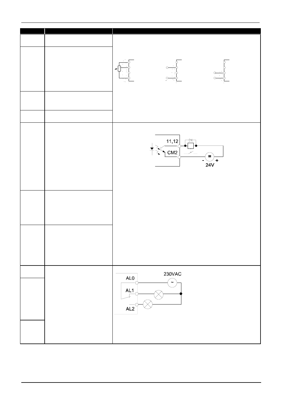
H
10 V reference voltage for
frequency command default
O
Analog input
Frequency command
0-10 V
3RWHQWLRPHWHU
WR N2KP
,QSXW LPSHGDQFH
N2KP
,QSXW LPSHGDQFH
2KP
+
2
2,
/
+
2
2,
/
+
2
2,
/
P$
9
3(
3(
3(
QRPLQDO 9
QRPLQDO P$
OI
Analog input
Frequency command
4-20 mA
For analog input reference adjustment see parameters
A11...A16.
Input OI for 4-20 mA is activated when the digital input is set to [AT]
(see parameter
C01...C05
).
L
0 V reference potential for
frequency command inputs
If no digital input is programmed as [AT] (switch frequency
command 0-10 V / 4-20 mA), the set values are added to O and OI.
CM2
Reference potential for output
11, 12
Transistor output, max. 27 VDC, 50 mA
The outputs can be programmed as NC contacts or NO contacts
under parameter
C31 or C32
(factory default: NC contact)
11
Programmable
Digital output
Factory default: [FA1]
The following functions may be programmed under the
parameters
C21
and
C21
:
[FA1]: at frequency (Signal when the set value is reached)
[FA2]: above frequency (Signal if output frequencies >/= the
frequencies set under parameter
C42 or C43)
.
[RUN]: Running (Signal if output frequency >0 Hz)
12
Programmable
Digital output
Factory default: [RUN]
[OL]: Motor overload (Signal if the motor current exceeds the value
set under parameter
C41
).
[OD]: PID-deviation (Signal if the deviation between the set value
and the actual value returned is greater than the value set
under parameter
C44
. Only available if the PID controller -
parameter
A71-
is active).
[AL]: Fault (Signal if a fault is indicated. See parameter
C21, C22
)
AL2
AL1
AL0
Relay output
Collective fault
Operation: AL0-AL1 closed
Fault, power off: AL0-AL2 closed (parameter
C33
)
The fault indication relay is set with a time delay of approx. 2 s after
the power is switched on.
250 VAC, 2.5 A resistive
0.2 A cos
∅
= 0.4
30 VDC, 3.0A resistive
0.7 A cos
∅
= 0.4
min. 100 VAC, 10 mA
5 VDC 100 mA