Attention – Rockwell Automation 161 SERIES A User Manual
Page 15
Bulletin 161
9
ATTENTION
•
If an input is used as [FW] or [RV] and programmed as a Normally Closed (NC) contact, the drive will
start as soon as the power supply is switched on – without the input being triggered.
•
Please note that a start command should not be issued if an input is used as [FW] or [RV] when the
power is switched on otherwise the motor will start immediately; wait at least 2s after switching on
the power before issuing a start command.
Terminal
Function
Description
FM
Programmable output
Output frequency or
Motor current
Analog signal (0-10 V, 1 m A)
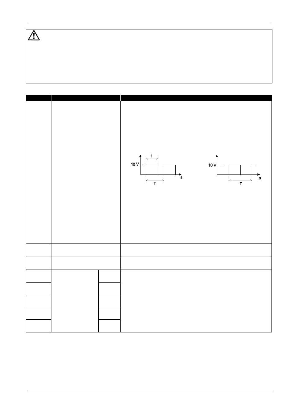
The output frequency output is available as a pulse signal. In the
factory default the frequency is an analog signal (0-10 V),
corresponding to 0 Hz to the max. frequency.
(Match the signal under parameter
b81
; programming under
parameter
C23
).
analog signal,
pulse signal (frequency)
frequency or current
duty cycle approx. 50%
T = 4 ms (const.)
Analog signal: The relation t/T changes in proportion to the
frequency (or to the current). The maximum voltage of 10 V is
reached with the max. frequency (or 200% rated current)
(100% In
⇒
5 V, 200 In
⇒
10 V, accuracy approx. +/-5%
for the frequency indicator and 20% for drive current indicator.
Pulse signal: frequency = output frequency x factor of the
multiplied frequency indicator (param.
b86
, factory default = 1),
max. frequency 3.6 kHz.
L
0 V
0 V potential for output FM
P24
24 V
24 V potential for digital inputs 1, 2, ... , 5
max. load 30 mA
5
[RS]
4
[CF2]
3
Programmable
digital inputs
[CF1]
2
[RV]
1
[FW]
Inputs 1 ... 5 are programmable. An overview of the possible
functions can be found on pages 11 and 12.
This table contains the basic setting for the terminal connections.
It is not possible to program two inputs with the same function at the
same time (see parameter
C01...C05
)
Inputs 1 ... 5 – with the exception of the reset and PTC input may
be programmed as either a NC contact or a NO contact (see
parameter
C11...C15
).