Ethernet link leds link 1 and 2, Self-test via ethernet/ip, Warnings, alarms and errors via ethernet/ip – Rockwell Automation 842E EtherNet/IP Absolute Encoder User Manual User Manual
Page 53
Rockwell Automation Publication 842E-UM001A-EN-P May 2012
45
Diagnostics and troubleshooting
Chapter 7
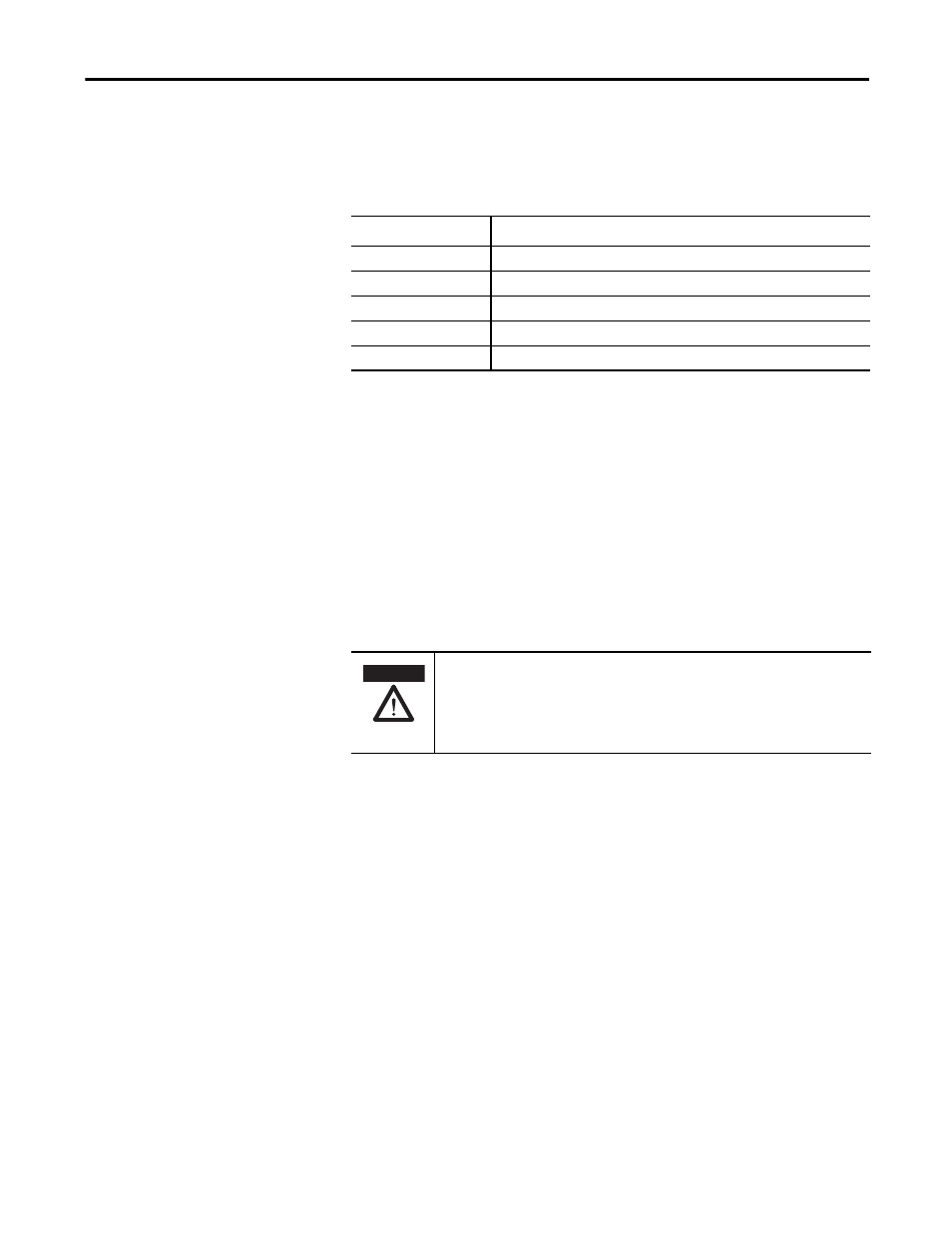
Ethernet Link LEDs Link 1 and 2
The ethernet link LEDs, Link 1 and Link 2, display the status of the physical
connection on the ethernet interface.
Self-test via EtherNet/IP
Electromagnetic interference (EMI) can cause incorrect operations or errors in
the position value. Without a self-test an immediate position change may occur
on power up.
Using the position sensor object a self-test can be triggered with attribute 13. See
“CIP object model” on page 12. During this test the sensor and the most
important functions are tested automatically. If an error occurs, bit 27 in the fault
header is set.
Warnings, alarms and errors
via EtherNet/IP
Within EtherNet/IP warnings, alarms, and errors can be retrieved using implicit
messages and also explicit messages.
Alarms and warnings for the encoder can be read via the position sensor object
with the aid of the attributes.
For errors, alarms, and warning the following applies:
Bit status = 0: no error, alarm or warning
Bit status =1: error, alarm or warning present
In addition the Net LED illuminates red continuously.
Link 1 or Link 2 LED
Description
OFF
No link / power off
Green solid
Ethernet connection established
Green flashing
Data transmission TxD/RxD
Amber solid
Interface port locked
Amber flashing
Data collisions
ATTENTION
It is imperative to evaluate the alarms in your application!
In case of a serious error, incorrect position values may be output. This change
could cause an unexpected movement that may result in a hazard for persons or
damage to the system or other objects.