Mechanical specifications, Electrical, Electrical wiring instructions – Rockwell Automation 842E EtherNet/IP Absolute Encoder User Manual User Manual
Page 27
Rockwell Automation Publication 842E-UM001A-EN-P May 2012
19
Installation
Chapter 4
9.
Remove the screw cover on the back of the encoder and press the preset
push button to change the preset value to the current shaft position value.
(The factory preset value is zero.)
10.
Replace the screw cover.
Mechanical specifications
Electrical
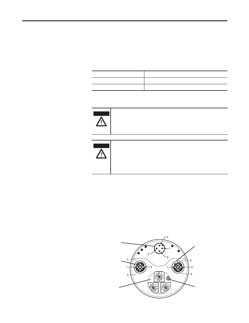
Electrical wiring instructions
Three electrical connections are located on the back of the housing.
A 4-pin M12 connector is used for the power supply connection.
Two 4-pin M12 connectors are used for the ethernet connection. The Link 1
connection is used for star networks. For ring networks, use both the Link 1 and
Link 2 connectors. In a linear network, use Link 1, Link 2, or both connectors.
Face mount flange
10 x 19 mm
Servo flange
6 x 10 mm
Blind hollow shaft
8, 19, 12, 15 mm and 1/4, 1/2, 3/8, 5/8 in.
ATTENTION
Switch off the power supply. The machine/system could unintentionally start
while you are connecting the devices.
Ensure that the entire machine/system is disconnected during the electrical
installation.
ATTENTION
Commissioning requires a thorough check by authorized personnel!
Before you operate a system equipped with the 842E EtherNet/IP absolute
encoder, make sure that the system is first checked and released by authorized
personnel.
Please read more in Chapter 1, Safety.
Net
Mod
Link 1
Link 2
Encoder
Network
Address
Switches
x1
x10
x100
Reset
Button
Power connection
Link 1 connection
Network address
switches
Link 2 connection
Preset push button