TerraWave BTRM-200 User Manual
Page 5
VENTEV INNOVATIONS BTRM200 Battery Test Remote Monitoring System – User Guide V1.0
5
4. System Description
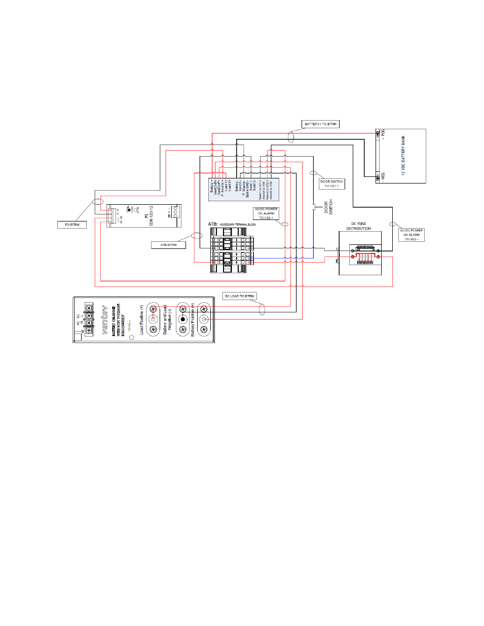
4.1. Overall System Connection Diagram
4.2. System Connector Overview
4.2.1. Power Supply In Power Jack (P. Source +/ - and VenCh P+)
The BTRM must be connected to the load power supply in order to energize the
load while the battery charger is charging the battery.
4.2.2. Battery Charger In Power Jack (VenCh B+/ -)
The BTRM must be connected to the battery charger in order to charge the
battery bank after the battery capacity test is performed.
4.2.3. Battery In Power Jack (Battery +/-)
The battery bank must be connected directly to the BTRM in order to perform
the battery capacity test.
4.2.4. Alarm Connector (Alarm1 or I/O1, Alarm2 or I/O2)
BTRM has two independent, isolated relay contacts for alarm indication.
Contacts are normally open when power is off. The user can select normally
open or normally closed under an alarm condition. Do not exceed the contact
- T49080O10007B (2 pages)
- T49120O10006 (2 pages)
- T24235G10006T (2 pages)
- T58230P10006GPMT (2 pages)
- M5090090O10007S (2 pages)
- M6060060MP13602 (2 pages)
- M6060070P23620 (2 pages)
- T58070P23620 (2 pages)
- T58070P23602 (2 pages)
- T58070MP13620 (2 pages)
- T58160P10006-90D (1 page)
- T58150P10006120 (2 pages)
- T58170P1000690 (2 pages)
- M6060070P23602T (2 pages)
- M5120120P10006180 (2 pages)
- M5150150P10006120 (2 pages)
- M5160160P10006 (2 pages)
- M5170170P1000660 (2 pages)
- TWS2400-TNC (1 page)
- TWS2400 (1 page)
- TWS2400-5-RPSMA (1 page)
- TWS2400-5-RPTNC (1 page)
- T24070R10020B (1 page)
- T24070R10002B (1 page)
- T58050R10020 (1 page)
- M6020020R1D0002 (1 page)
- V10082-HRE-NEB (3 pages)
- TW-HE-06042-PL (2 pages)
- TW-HE-06042-PR (2 pages)
- M6140140MP1D0006 (2 pages)
- M6100110MP1D1806 (2 pages)
- M6100110MP1D0006 (2 pages)
- M6060060MP1D43602 (3 pages)
- M6060060P1D63620V (3 pages)
- M6060060MP1D33602 (2 pages)
- T24120P10006180 (2 pages)
- T24125P10006120 (2 pages)
- T24130P10006GT (2 pages)
- T24135P10006120 (2 pages)
- T24140P1000690 (2 pages)
- T24140P10006-90 (2 pages)
- T24150P1000660 (2 pages)
- T24190P10006GT (2 pages)
- T24050P13602-135 (2 pages)
- T24060MP13620 (2 pages)