SATEC ETC2002 User Manual
Page 18
Chapter 3 Operating the ETC2002
Using the ETC2002
18
ETC2002 Network Communicator
updates from the ETC2002 clock, which may be synchronized with the
precise satellite GPS clock using an optional IRIG-B input.
Acquired real-time data is normally stored in the ETC2002 exchanges. If the
user wishes, acquired data can be periodically moved to historical circular
files where data is kept for a long time until it is overwritten by newer data.
Data is recorded to historical files at regular intervals. To enable logging,
specify a non-zero logging interval in the Data Server Options setup (see
in Chapter 5). The logging interval is always
represented as a whole number of data polling intervals even if the polling
itself is not synchronized with polling intervals, such as in the event of
continuous polling. Since the ETC2002 attempts to synchronize polling
devices with the beginning of an hour, it is recommended to program a
logging interval in such a manner that it is a whole divisor of 60 minutes.
Historical records can be read in an arbitrary manner, or in a sequential
order. See the ETC2002 Modbus Guide for more information on retrieving
log files from your device.
Status Event Exchanges
The Data server logs binary events asserted by the connected devices and
gives notification to the eXpertPower server.
A binary event mask specifies critical event bits in the device status register.
Whenever the Data server detects a change in the status bits selected by the
event mask, it records an event record to the circular Event log file. If the
eXpertPower service is enabled in the ETC2002, this event initiates a
connection to the eXpertPower server.
Polling status events is performed via the status event exchanges. The Data
server provides up to 250 event exchanges of 1 register long, with a
separate event mask.
The Data server provides the auto re-set option that may be used to clear a
latched device status register after it has been read. In most devices, critical
events are latched into a status register, so that the new events are not
generated until the register is explicitly cleared by a master application.
Since status registers may be implemented in the device either as coils, or
as holding registers, you should specify a register type for each event
exchange.
Write Data Exchanges
The Data server can provide remote writing data to serviced devices upon
user request. Up to 250 write exchanges are supported with a size of 1 to 12
registers.
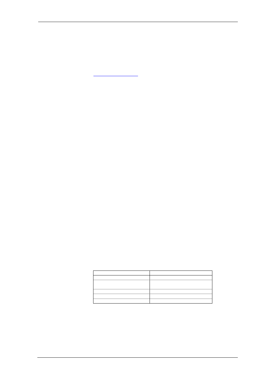
The following table shows the write exchange layout.
Write Exchange Block
Description Range
Exchange number
0-249
Write flag
0 – Data has been written
1 – Data is waiting to be written
Data register 1
...
Data register 12
To send data to a device via a write exchange, write data to the write
exchange with the write flag being set to 1. The write flag is automatically
cleared after the data has been successfully transferred to the device.
Always check this flag before writing new data to the exchange to ensure it is
empty, otherwise previously written data may be lost.