Case, Sensor – RKI Instruments Gas Tracer 10,000 ppm User Manual
Page 13
10,000 ppm Gas Tracer Operator’s Manual
Instrument Description • 6
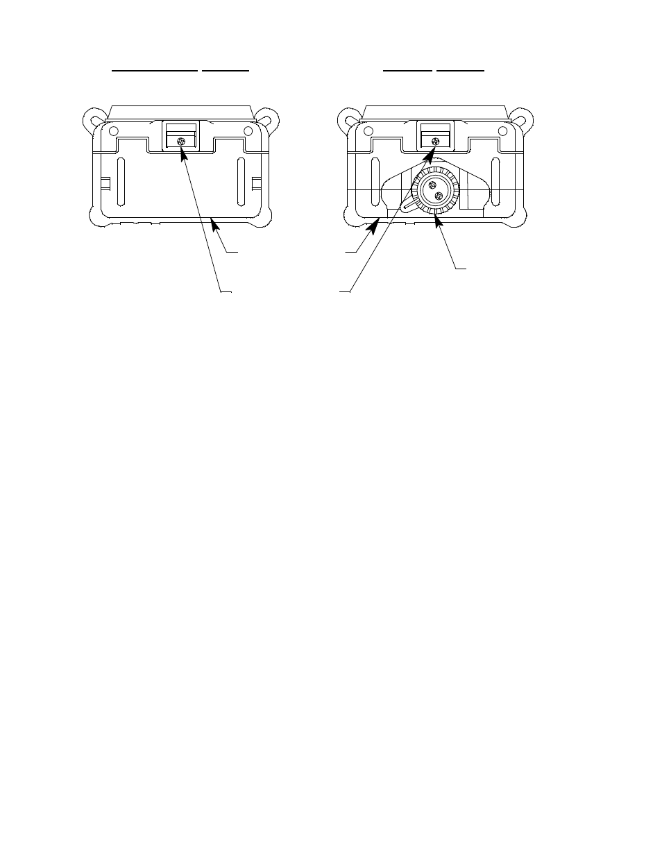
Figure 2: Components of the Gas Tracer, Bottom
Case
The Gas Tracer’s sturdy, high-impact plastic case is radio frequency
(RF) resistant and is suitable for use in many environmental
conditions, indoors and out. The case is dust proof and weather
resistant. A rubber layer on the outside of the case protects it from
scratches and impact damage.
A clear plastic window through which the LCD can be viewed is
located on the front of the case. Four brass charging contacts that are
used when the Gas Tracer is placed in the charging station are on the
back of the case. Both the rechargeable and alkaline version include a
removable battery pack. The battery pack release latch is on the
bottom. The alkaline battery version also includes a battery cover
release knob. The battery pack and flow chamber are located on the
back of the Gas Tracer. The inlet filter holder is located on the top of
the Gas Tracer case.
Sensor
The Gas Tracer has only the ppm sensor installed. All other sensor
positions are filled with a dummy sensor. The ppm sensor is located
inside the Gas Tracer and is held in its socket by the flow chamber.
The ppm combustible sensor detects combustible gas in the ppm
range. It is a combination catalytic/MOS type sensor with a current
output. The current is amplified by the Gas Tracer’s circuitry,
converted to a measurement of combustible gas concentration, and
Rechargeable Version
Battery Pack
Battery Pack
Release Latch
Battery Cover
Release Knob
Alkaline Version