Appendix pinout – Opticon RFS 6000 User Manual
Page 12
U
SER
’
S
& S
ET UP MANUAL
RFS 6000
12
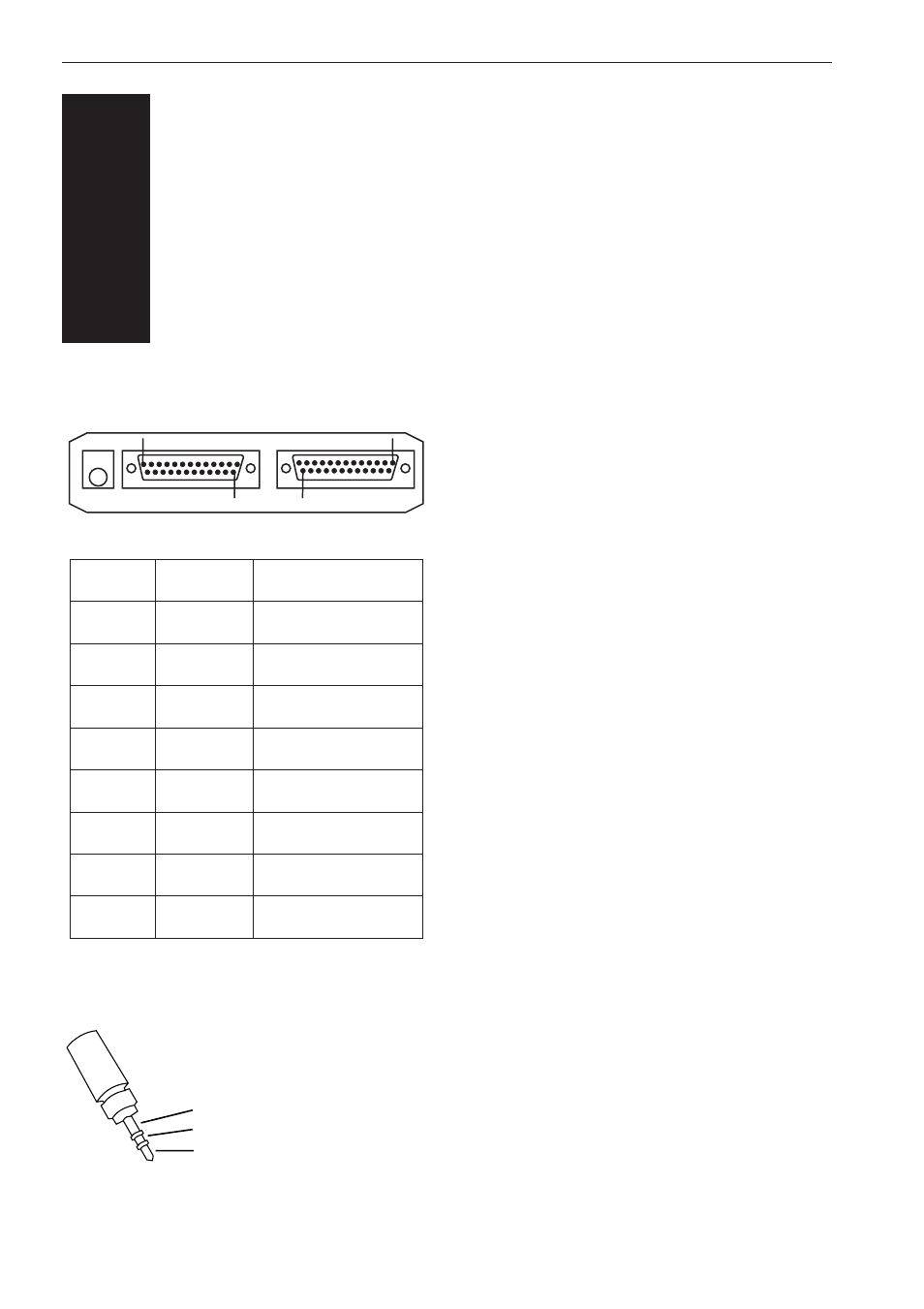
Pinout description of connectors of the
controller which can be used for connection:
Pinout description of the 5 V power plug:
APPENDIX
PINOUT
3
A
PIN
1
2
3
4
5
7
9 / 11
10 / 12
IN/OUT
-
OUT
IN
OUT
IN
-
IN / OUT
IN / OUT
FUNCTION
FRAME GROUND
RS232 TxD
RS232 RxD
RS232 RTS
RS232 CTS
SIGNAL GROUND
RS485 Tx/Rx +
RS485 Tx/Rx -
DB 25 FEMALE
DB 25 MALE
1
1
25
25
3.5 MM
STEREOPLUG
0 V
+5 V
Not connected
See also other documents in the category Opticon Equipment:
- С-37 Universal menubook (151 pages)
- С-37 (8 pages)
- CHG 3101 (2 pages)
- CRD 3101 (4 pages)
- CRD 13 (4 pages)
- CRD 15 (1 page)
- CRD 1531 (1 page)
- CRD 19 E4 (1 page)
- CRD 19 E4 AdminTool (11 pages)
- DCL 153X (23 pages)
- OPL 972X (23 pages)
- DFM 1000 (20 pages)
- DWT 7133 (9 pages)
- ECB 1000 (12 pages)
- ESL (40 pages)
- H13 (4 pages)
- H15 Quick Guide (2 pages)
- H15 User Manual (101 pages)
- H16 End User License Agreement for Microsoft Software (8 pages)
- H16 Quick Guide (2 pages)
- H16 User Manual (160 pages)
- H19 User Manual (192 pages)
- H19 Cradle User Manual (2 pages)
- H19 Quick Guide (2 pages)
- H19 car kit Quick Guide (1 page)
- H21 (103 pages)
- H22 (110 pages)
- M5 (4 pages)
- OPD 7124 brief setup (4 pages)
- OPH 1003 (2 pages)
- OPH 1004 (2 pages)
- OPH 1005 (2 pages)
- OPI 2101 (4 pages)
- OPI 4002 (26 pages)
- OPL 9713 (1 page)
- OPL 9724 Bluetooth Print (9 pages)
- OPL 9724 (29 pages)
- OPL 9728 (19 pages)
- OPM 1736B (8 pages)
- OPN 2001 User Manual (11 pages)
- OPN 2001 Device Parameters (3 pages)
- OPN 2002 v35315 Bluetooth demo Quick Guide (13 pages)
- OPN 2002 v35412 Batch demo Quick Guide (14 pages)
- OPN 2002 v35106 Bluetooth OPN2001 simulation Quick Guide (11 pages)
- OPN 2002 Quickstart Guide for iPhone or iPad (2 pages)