Positioning the crosshead to install the specimen – MTS Landmark System User Manual
Page 54
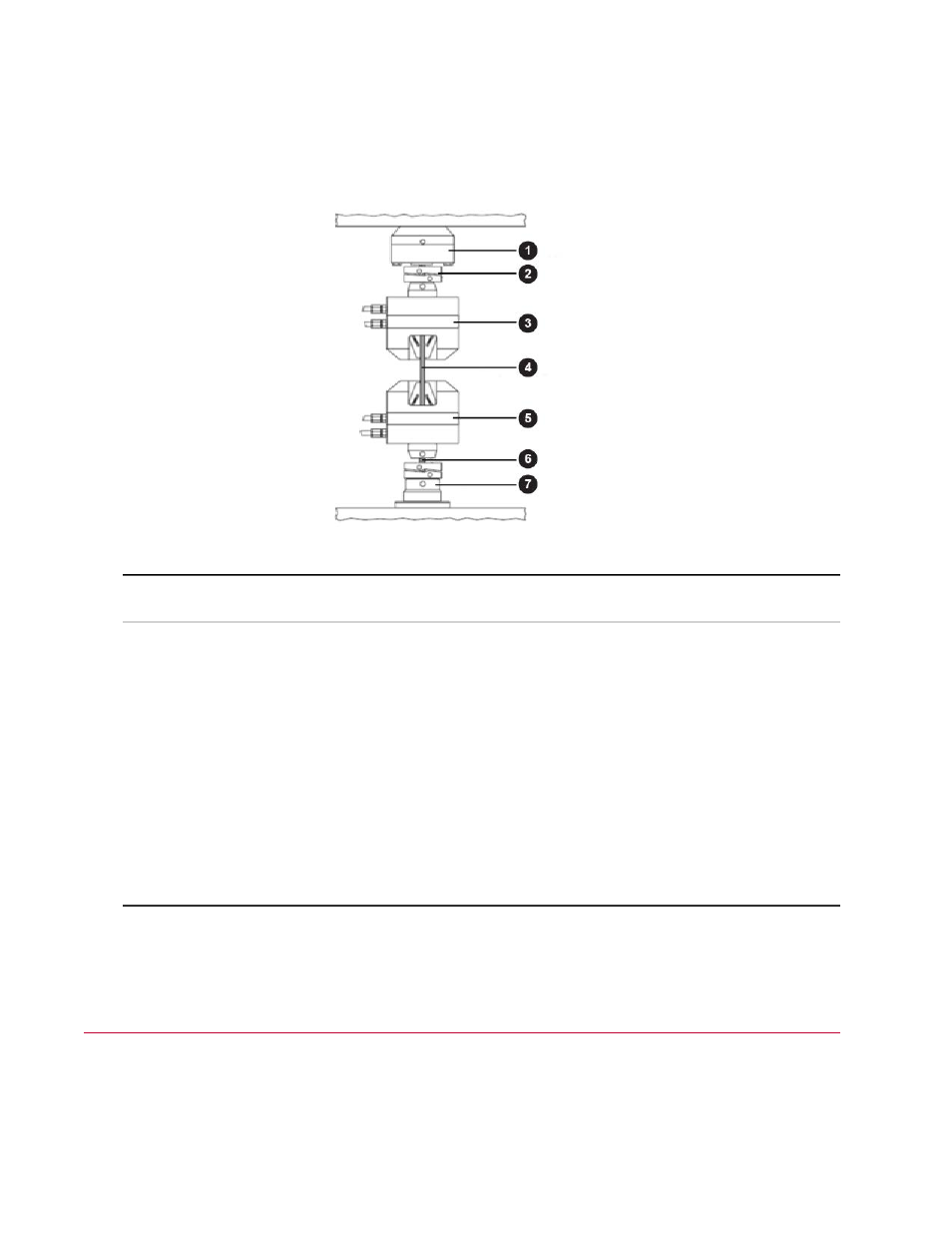
For load frames with base mounted actuators (as used by the typical system in this manual), the load train
consists of all the components between the actuator’s piston rod (the component that moves up and down)
and the crosshead. This typically includes the lower grip, the specimen, the upper grip, and the force
sensor (load cell), as shown.
Typical Components in the Load Train
Description
Item
Force Sensor (Load Cell)
1
Spiral Washers
2
Upper Grip
3
Specimen
4
Lower Grip
5
Connector Stud
6
Actuator
7
Positioning the Crosshead to Install the
Specimen
You may have to position the crosshead up or down to accommodate the dimensions of the specimen
and grips within the load train. In general, once you position the crosshead, additional adjustments are not
54 | MTS Landmark Test System Operation
Key Concepts