2 leds, 3 faults, 1 fault codes – Lenze S94P01B2 User Manual
Page 68: Diagnostics 8.2 leds
S94P01B2
66
Diagnostics
8.2
LEDs
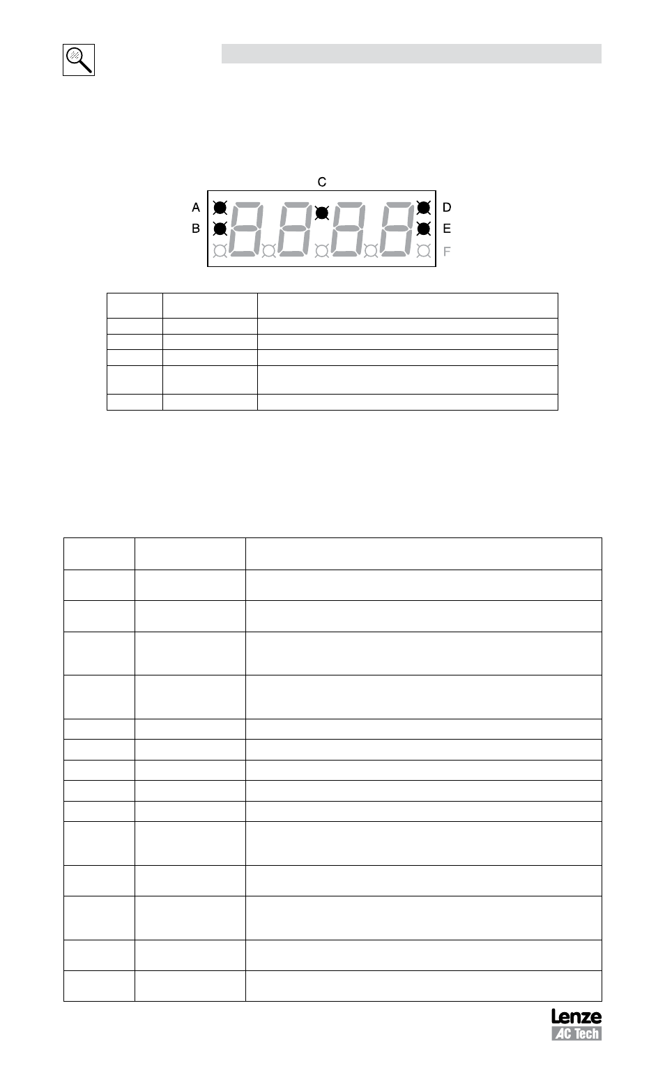
The PositionServo has five diagnostic LEDs mounted on the periphery of the front
panel display as shown in the drawing below. These LEDs are designed to help monitor
system status and activity as well as troubleshoot any faults.
S913
LED
Function
Description
A
Enable
Orange LED indicates that the drive is ENABLED (running).
B
Regen
Yellow LED indicates the drive is in regeneration mode.
C
Data Entry
Yellow LED will flash when changing.
D
Comm Fault
Red LED illuminates upon a communication fault.
(available in CANbus only)
E
Comm Activity
Green LED flashes to indicate communication activity.
8.3
Faults
8.3.1 Fault Codes
Listed herein are fault codes caused mostly by hardware operations. Additional fault
codes are listed in the PositionServo Programmer’s manual.
Fault Code
(Display)
Fault
Description
F_OU
Over voltage
Drive bus voltage reached the maximum level, typically due to motor
regeneration
F_FB
Feedback error
Invalid Hall sensors code; Resolver signal lost or at least one motor hall
sensor is inoperable or not connected.
F_OC
Over current
Drive exceeded peak current limit. Software incapable of regulating
current within 15% for more than 20mS. Usually results in wrong motor
data or poor tuning.
F_Ot
Over temperature
Drive heatsink temperature has reached maximum rating.
Trip Point = 100°C for all drives except 480V 6A & 9A drives
Trip Point = 108°C for 480V 6A & 9A drives
F_OS
Over speed
Motor has reached velocity above its specified limit
F_PE
Position Error Excess Position error has exceeded maximum value.
F_bd
Bad motor data
Motor profile data is invalid or no motor is selected.
F_EP
EPM failure
EPM failure on power up
-EP-
EPM missing
EPM not recognized (connected) on power up
F_09
Motor over
temperature
Motor over temperature switch activated; Optional motor temperature
sensor (PTC) indicates that the motor windings have reached maximum
temperature
F_10
Subprocessor failure
Error in data exchange between processors. Usually occurs when EMI
level is high due to poor shielding and grounding.
F_14
Under voltage
Occurs when the bus voltage level drops below 50% of nominal bus
voltage while drive is operating. An attempt to enable the drive with low
bus voltage will also result in this fault
F_15
Hardware overload
protection
Occurs when the phase current becomes higher than 400% of total drive’s
current capability for more then 5ms.
F_18
Arithmetic Error
Division by zero
Statement executed within the Indexer Program results in a division by 0
being performed. Drive programming error (error in drive source code).