2 p2 - serial communications port, 3 p3 - controller interface, Interface – Lenze S94P01B2 User Manual
Page 18: P2 rs-232
S94P01B2
16
Interface
P7 PIN ASSIGNMENTS (OUTPUT POWER)
Pin
Terminal Function
1
T1
Thermistor (PTC) Input
2
T2
Thermistor (PTC) Input
3
U
Motor Power Out
4
V
Motor Power Out
5
W
Motor Power Out
6
PE
Protective Earth (Chassis Ground)
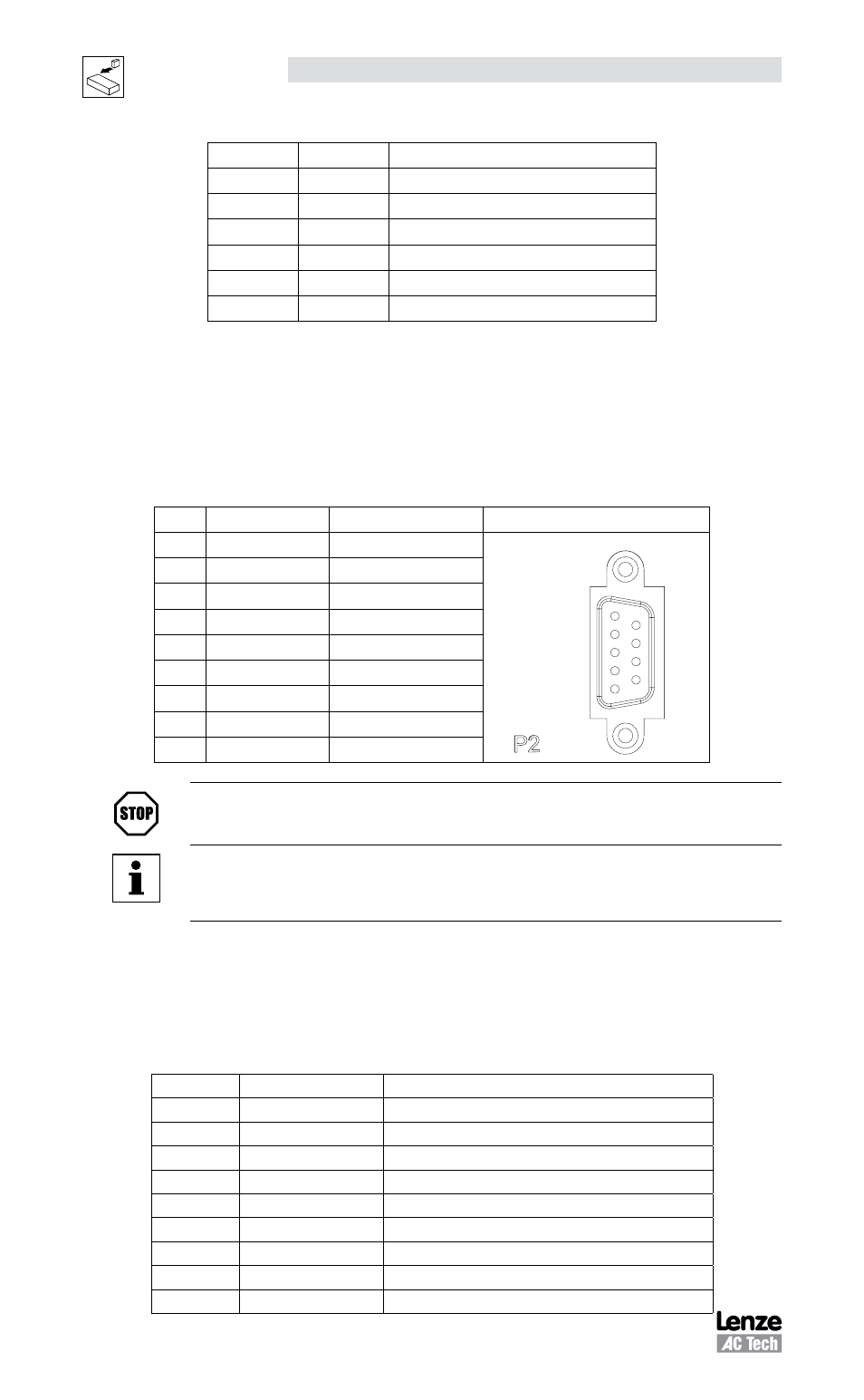
4.1.2 P2 - Serial Communications Port
P2 is a 9-pin D-sub connector that is used to communicate with a host computer via
standard RS-232 interface using a proprietary Point-to-Point Protocol (PPP). This port
is present on all Model 94 and 940 RS-232-based drives. All levels must be RS-232C
compliant.
P2 PIN ASSIGNMENTS (COMMUNICATIONS)
Pin
Name
Function
RS-232 Connector
1
Reserved
P2
RS-232
1
5
9
6
2
TX
RS-232 (transmit)
3
RX
RS-232 (receive)
4
Reserved
5
GND
Common
6
Reserved
7
Reserved
8
Reserved
9
Reserved
STOP!
Do not make any connection to Reserved pins!
NOTE
If you purchase serial cables from a third party, you must use a pass-
through cable, not Null-Modem (not crossover)
4.1.3 P3 - Controller Interface
P3 is a 50-pin SCSI connector for interfacing to the front-end of the controllers. It is
strongly recommended that you use OEM cables to aid in satisfying CE requirements.
Contact your Lenze representative for assistance.
P3 PIN ASSIGNMENTS (CONTROLLER INTERFACE)
Pin
Name
Function
1
MA+
Master Encoder A+ / Step+ input
(2)
2
MA-
Master Encoder A- / Step- input
(2)
3
MB+
Master Encoder B+ / Direction+ input
(2)
4
MB-
Master Encoder B- / Direction- input
(2)
5
GND
Drive Logic Common
6
5+
+5V output (max 100mA)
7
BA+
Buffered Encoder Output: Channel A+
(1)
8
BA-
Buffered Encoder Output: Channel A-
(1)
9
BB+
Buffered Encoder Output: Channel B+
(1)