3 analog i/o details, 1 analog reference input, 2 analog output – Lenze S94P01B2 User Manual
Page 27: Interface 4.3 analog i/o details
S94P01B2
25
Interface
4.3
Analog I/O Details
4.3.1 Analog Reference Input
AIN+, AIN1- (P3.24 and P3.25)
The analog reference input can accept up to a ±10V analog signal across AIN1+ and
AIN2-. The maximum limit with respect to analog common (ACOM) on each input is
±18VDC. The analog signal will be converted to a digital value with 16 bit resolution (15
bit plus sign). This input is used to control speed or torque of the motor in velocity or
torque mode. The total reference voltage as seen by the drive is the voltage difference
between AIN1+ and AIN1-. If used in single-ended mode, one of the inputs must
be connected to a voltage source while the other one must be connected to Analog
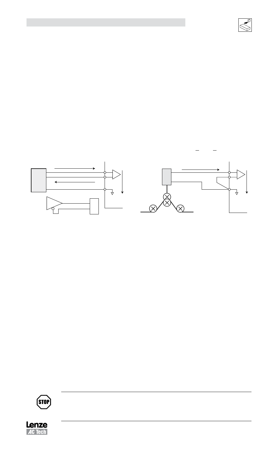
Common (ACOM). If used in differential mode, the voltage source is connected across
AIN+ and AIN- and the driving circuit common (if any) needs to be connected to the
drive Analog Common (ACOM) terminal.
Reference as seen by drive: Vref = (AIN1+) - (AIN1-) and -10V < Vref < +10V
External Reference
(Differential Configuration)
ACOM
Analog Command Output
Analog Command Return
ACOM
P3 24
P3 25
P3 22
AIN
AIN+
PostionServo
Drive
940 Servo Drive
+
Analog input +
Analog input
A
nalog I
nput
Motion
Controller
Single-ended Configuration
ACOM
AOut
P3 20
P3 21
P3 22
AIN
A N+
PositionServo
Drive
ACOM
As the dancer arm goes up and down
a 0 10 vo t s gnal is transmitted
to the PositionServo Drive
+
Differential
mb105
Single-Ended
mb106
AIN2+, AIN2- (P3.20 and P3.21)
The analog reference input can accept up to a ±10V analog signal across AIN2+ and
AIN2-. The maximum limit with respect to analog common (ACOM) on each input is
±18VDC. The analog signal will be converted to a digital value with 10 bit resolution
(9 bit plus sign). This input is available to the User’s program. This input does not have
a predefined function. Scaling of this input is identical to AIN1.
4.3.2 Analog Output
AO (P3.23)
The analog output is a single-ended signal (with reference to Analog Common (ACOM)
which can represent the following Motor data:
• Not Assigned
• Phase R Current
• Iq current
• RMS Phase Current
• Phase S Current
• Id current
• Peak Phase Current
• Phase T Current
• Motor Velocity
Motor phase U, V and W correspond to R, S and T respectively.
MotionView Setup program can be used to select the signal source for the analog
output as well as its scaling.
If the output function is set to “Not Assigned” then the output can be controlled directly
from user’s program. Refer to the 940 Programming Manual.
STOP!
Upon application of power to the PositionServo, the Analog Output supplies
-10VDC until bootup is complete. Once bootup is complete, the Analog Output will
supply the commanded voltage.