Interface – Lenze S94P01B2 User Manual
Page 20
S94P01B2
18
Interface
The PositionServo 940 buffers encoder feedback from P4 to P3. Encoder Feedback
channel A on P4, for example, is Buffered Encoder Output channel A on P3. The Hall
sensors from the motor must be wired to the 15-pin connector (P4).
STOP!
Use only +5 VDC encoders. Do not connect any other type of encoder
to the PositionServo 940 reference voltage terminals. When using a
front-end controller, it is critical that the +5 VDC supply on the front-
end controller NOT be connected to the PositionServo 940’s +5 VDC
supply, as this will result in damage to the PositionServo 940.
NOTE
•
The PositionServo 940 encoder inputs are designed to accept
differentially driven hall signals. Single-ended or open-collector
type hall signals are also acceptable by connecting “HA+”, “HB+”,
“HC+” and leaving “HA-,HB-,HC-” inputs unconnected. You do not
need to supply pull-up resistors for open-collector hall sensors.
The necessary pull-up circuits are already provided.
•
Encoder connections (A, B, and Z) must be full differential.
PositionServo doesn’t support single-ended or open-collector type
outputs from the encoder.
•
An encoder resolution of 2000 PPR (pre-quadrature) or higher is
recommended.
Using P4 as second encoder input for dual-loop operation.
P4 can be used as a second loop encoder input in situations where the motor is
equipped with a resolver as the primary feedback. If such a motor is used, the drive
must have a resolver feedback option module installed. A second encoder can then be
connected to the A and B lines of the P4 connector for dual loop operation. Refer to
“Dual-loop Feedback Operation” for details (Section 6.4).
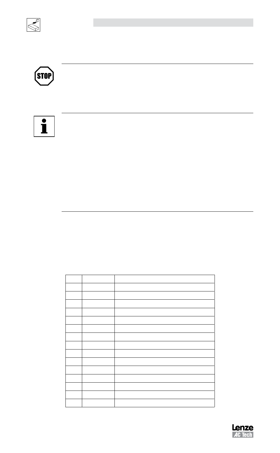
P4 PIN ASSIGNMENTS (ENCODER)
Pin
Name
Function
1
EA+
Encoder Channel A+ Input
(1)
2
EA-
Encoder Channel A- Input
(1)
3
EB+
Encoder Channel B+ Input
(1)
4
EB-
Encoder Channel B- Input
(1)
5
EZ+
Encoder Channel Z+ Input
(1)
6
EZ-
Encoder Channel Z- Input
(1)
7
GND
Drive Logic Common/Encoder Ground
8
SHLD
Shield
9
PWR
Encoder supply (+5VDC)
10
HA-
Hall Sensor A- Input
11
HA+
Hall Sensor A+ Input
12
HB+
Hall Sensor B+ Input
13
HC+
Hall Sensor C+ Input
14
HB-
Hall Sensor B- Input
15
HC-
Hall Sensor C- Input
(1)
See Note 1, Section 4.1.7 - Connector and Wiring Notes