2 digital outputs, Interface – Lenze S94P01B2 User Manual
Page 25
S94P01B2
23
Interface
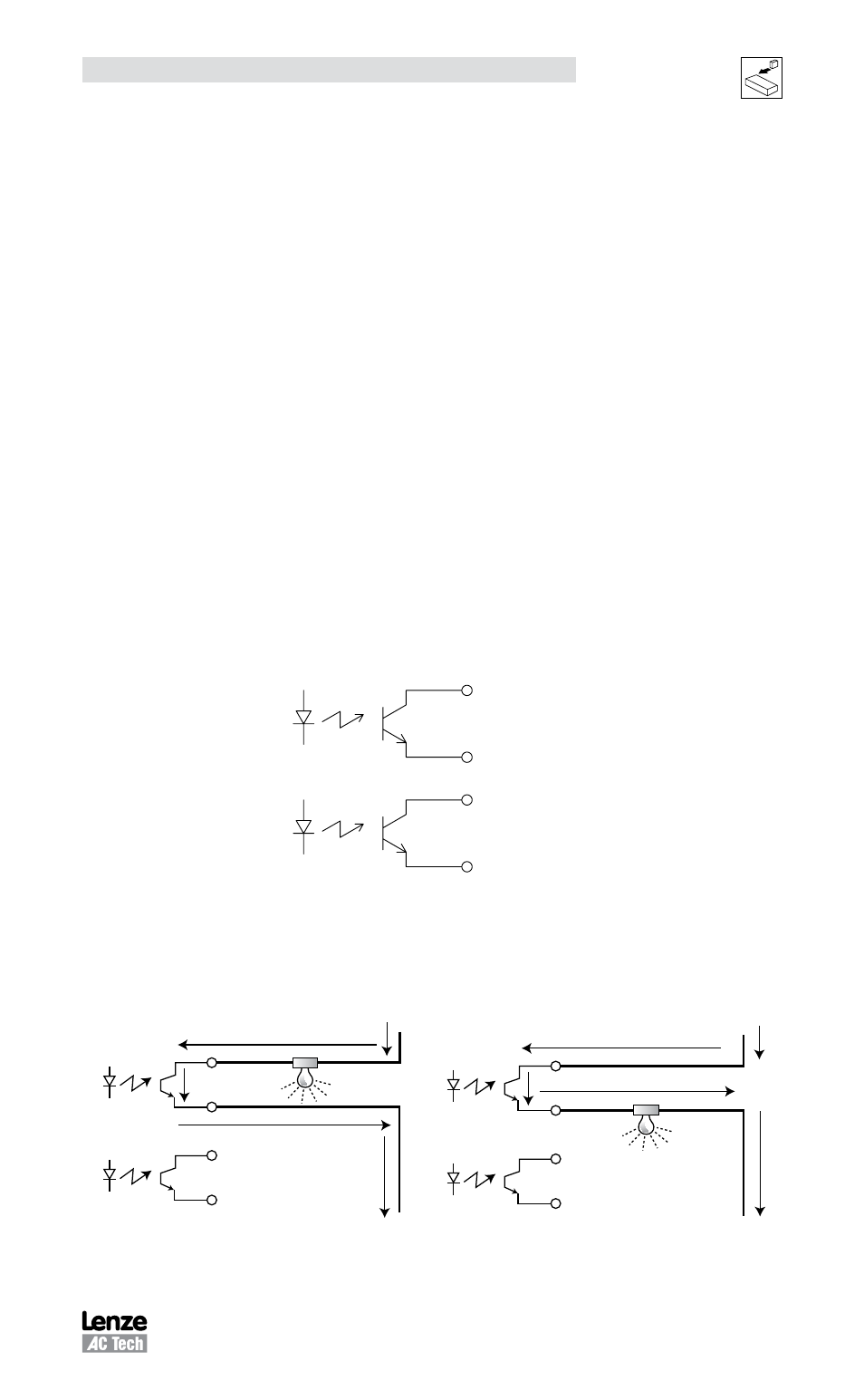
4.2.2 Digital Outputs
There are a total of five digital outputs (“OUT1” - “OUT4” and “RDY”) available on the
PositionServo 940 drive. These outputs are accessible from the P3 connector. Outputs
are open collector type that are fully isolated from the rest of the drive circuits. See the
following figure for the electrical diagram. These outputs can be either used via the
drives internal User Program or they can be configured as Special Purpose outputs.
When used as Special Purpose, each output (OUT1-OUT4) can be assigned to one of
the following functions:
•
Not assigned
•
Zero speed
•
In-speed window
•
Current limit
•
Run-time fault
•
Ready
•
Brake (motor brake release)
Please note that if you assign an output as a Special Purpose Output then that output
can not be utilized by the User Program. The “RDY” Output has a fixed function,
“ENABLE”, which will become active when the drive is enabled and the output power
transistors becomes energized.
Digital outputs electrical characteristics
Circuit type
Isolated Open Collector
Digital outputs load capability
15mA
Digital outputs Collector-Emitter max voltage
30V
OUT1-C
OUT1-E
OUT2-C
OUT2-E
43
44
45
46
S907
Digital outputs circuit
The outputs on the drive can be wired as either sinking (NPN) or sourcing (PNP) as
illustrated in wiring examples mb101 and mb102.
NPN Sinking
OUT 1-C
Gnd
+24V
49
44
45
46
OUT 1-E
OUT 2-C
OUT 2-E
PNP Sourcing
OUT 1-C
Gnd
+24V
49
44
45
46
OUT 1-E
OUT 2-C
OUT 2-E
mb101
mb102