4 p4 - motor feedback / second loop encoder input, Interface – Lenze S94P01B2 User Manual
Page 19
S94P01B2
17
Interface
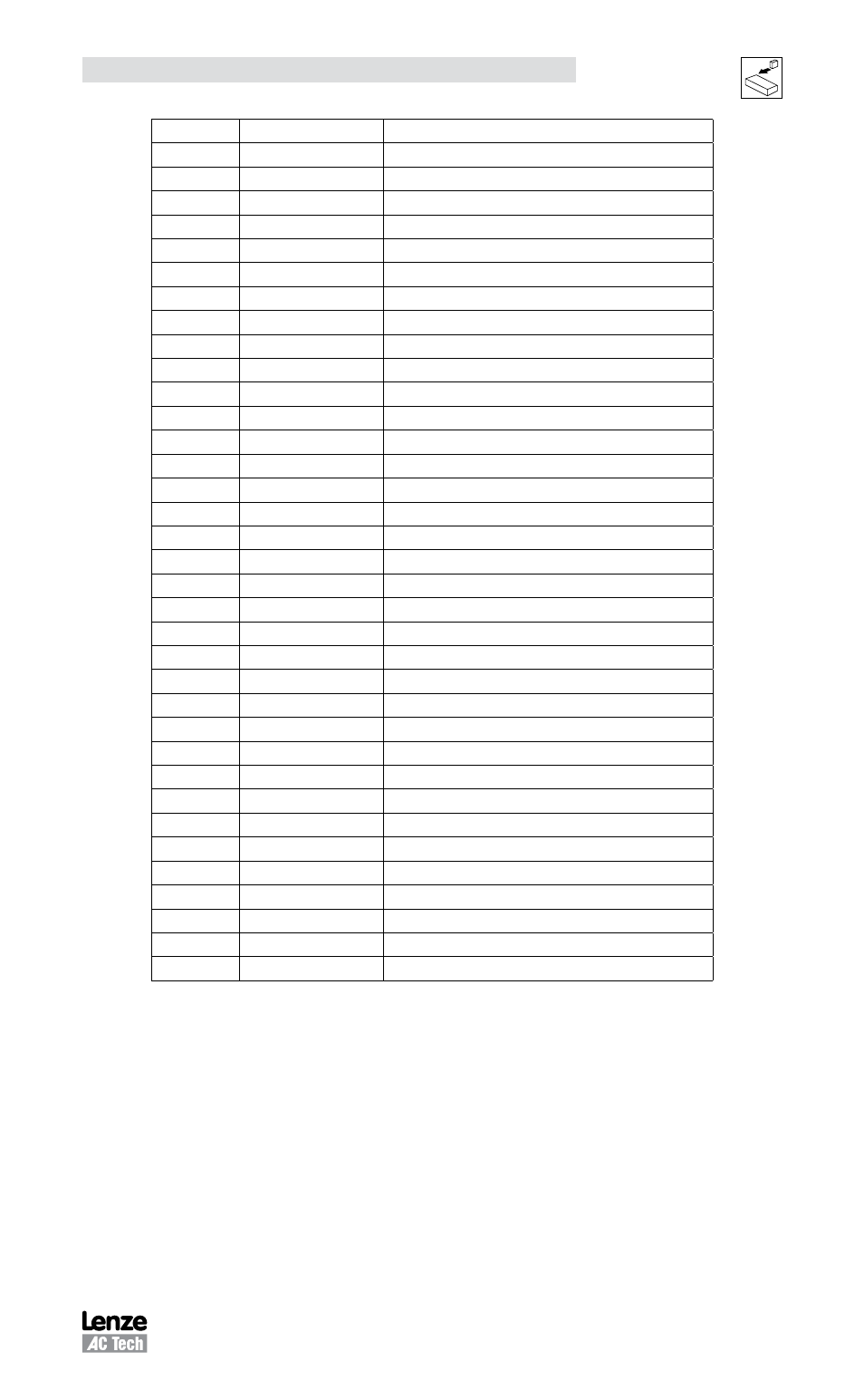
Pin
Name
Function
10
BB-
Buffered Encoder Output: Channel B-
(1)
11
BZ+
Buffered Encoder Output: Channel Z+
(1)
12
BZ-
Buffered Encoder Output: Channel Z-
(1)
13-19
Empty
20
AIN2+
Positive (+) of Analog signal input
21
AIN2-
Negative (-) of Analog signal input
22
ACOM
Analog common
23
AO
Analog output
24
AIN1+
Positive (+) of Analog signal input
25
AIN1 -
Negative (-) of Analog signal input
26
IN_A_COM
Digital input group ACOM terminal
(3)
27
IN_A1
Digital input A1
28
IN_A2
Digital input A2
29
IN_A3
Digital input A3
(3)
30
IN_A4
Digital input A4
31
IN_B_COM
Digital input group BCOM terminal
32
IN_B1
Digital input B1
33
IN_B2
Digital input B2
34
IN_B3
Digital input B3
35
IN_B4
Digital input B4
36
IN_C_COM
Digital input group CCOM terminal
37
IN_C1
Digital input C1
38
IN_C2
Digital input C2
39
IN_C3
Digital input C3
40
IN_C4
Digital input C4
41
RDY+
Ready output Collector
42
RDY-
Ready output Emitter
43
OUT1-C
Programmable output #1 Collector
44
OUT1-E
Programmable output #1 Emitter
45
OUT2-C
Programmable output #2 Collector
46
OUT2-E
Programmable output #2 Emitter
47
OUT3-C
Programmable output #3 Collector
48
OUT3-E
Programmable output #3 Emitter
49
OUT4-C
Programmable output #4 Collector
50
OUT4-E
Programmable output #4 Emitter
(1)
See Note 1, Section 4.1.7 - Connector and Wiring Notes
(2)
See Note 2, Section 4.1.7 - Connector and Wiring Notes
3)
See Note 3, Section 4.1.7 - Connector and Wiring Notes
4.1.4 P4 - Motor Feedback / Second Loop Encoder Input
P4 is a 15-pin DB connector that contains connections for Hall Effect sensors and
incremental encoder feedback. Refer to the P4 pin assignments table for the connector
pin assignments. Encoder inputs on P4 have 26LS32 or compatible differential receivers
for increased noise immunity. Inputs have all necessary filtering and line balancing
components so no external noise suppression networks are needed.
All conductors must be enclosed in one shield and jacket around them. Lenze
recommends that each and every pair (for example, EA+ and EA-) be twisted. In order
to satisfy CE requirements, use of an OEM cable is recommended. Contact your Lenze
representative for assistance.