Operation – Lenze S94P01B2 User Manual
Page 60
S94P01B2
58
Operation
Step 3: Setting the Position I-Gain and Position I-Gain Limit
The objective here is to minimize the position error during steady state operation and
improve positioning accuracy. Start to increase the Position I-gain. Increasing the I-gain
will increase the drive’s reaction time while the I-Limit will set the maximum influence
that the I-Gain can have on the Integral loop. When adjusting the I-gain start with a very
small value for the I-gain (e.g. 1) then increase the I-gain parameter value until stand-
still error is compensated and positioning accuracy is satisfactory. Remember that large
values of Position I-limit can cause a large instability in the control loop and unsettled
oscillation of the system mechanics.
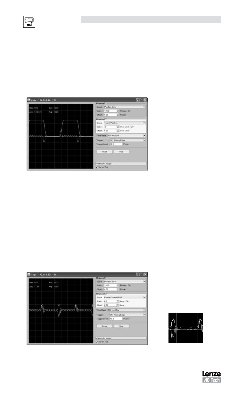
Position Error trace following the tuning of
Position P-, I- and D-Gains
Step 4: Check Motor Currents
Set the oscilloscope channel 2 to ‘Phase Current RMS’
Channel 2:
Signal
= “Phase Current RMS”
Scale
= as appropriate to peak current limit set in drive parameters (MotionView)
Timebase: = as appropriate to the “Period” of the moves being generated
Trigger:
= Ch1 Rising Edge
Level:
= 10 Pulses
Observe the Current waveform to make sure that there are no significant oscillations
during the steady state sections of the position profile (times when target position is not
changing). If so then decrease the gains values until the oscillations are either removed
or reduced to an acceptable level.
Minimal oscillation when motor positioned to
target position.