Led displays, Led supply module, Led axis module – Lenze 9228E User Manual
Page 80
78
2.
LED displays
The LED displays clearly indicate the momentary operating state of
the controller even from greater distances. The axis modules are
provided with 3 LEDs in the operating terminal, the supply has 2
LEDs at the front side.
2.1.
LED supply module
RDY
Ready to operate
The LED is illuminated after the ON-delay has passed and no fault
was detected. RDY is not illuminated if a fault was detected.
BR
on
Brake chopper active
The LED is illuminated if the DC bus voltage is increased above a
threshold by absorbing regenerated energy and then dissipated
through the brake resistor.
2.2.
LED axis module
RDY
Ready to operate
The LED is illuminated if the ON-delay has passed and no fault was
detected. RDY is not illuminated if a fault was detected or homing is
not finished or the DC bus control is active or a following error is
active.
I
max
The LED is illuminated when reaching the maximum controller
current or the set torque limit.
IMP
Pulse inhibit. The LED is illuminated if the inverter is inhibited. The
inverter is inhibited if the terminal 28 is low the STOP key is
pressed, inhibit avtivated by communication or if a fault is detected.
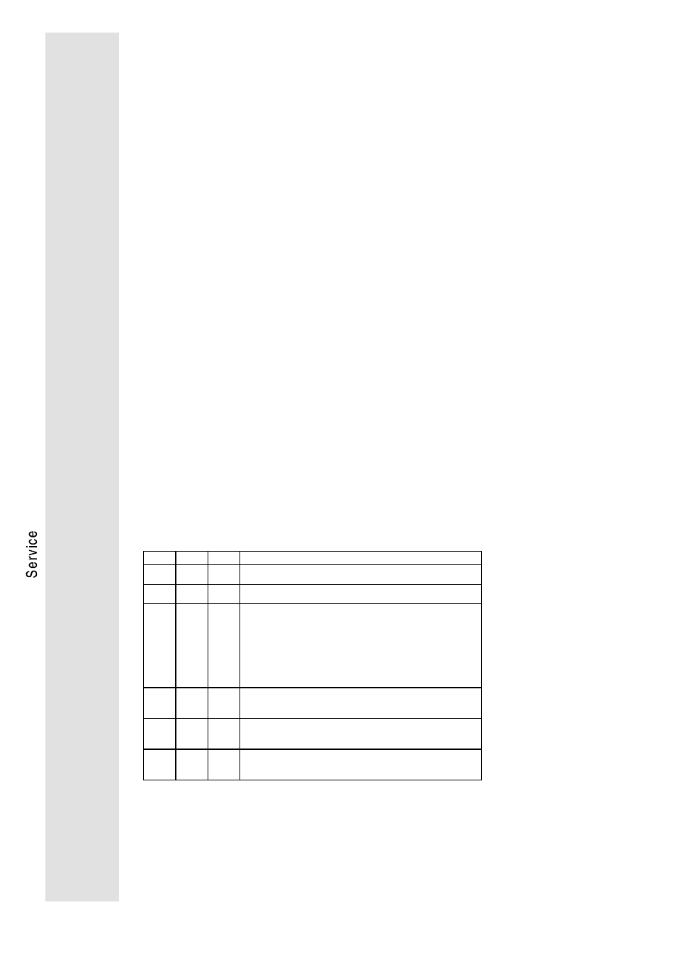
RDY
Imax
IMP
on
off
off
Controller is ready to operate, the controller is enabled
on
off
on
Controller is ready to operate, however, it is not enabled
on
on
off
Speed controller is limited:
the controller supplies the set maximum current
First commissioning:
If the motor speed remains at 50...300 rpm even at high
set value and low load, the motor connection cables U and
V must be exchanged.
off
off
on
Controller is not ready to operate. In case of fault, the type
of fault is displayed.
off
off
off
Maximum following error, homing not finished, active DC -
bus control (see above)
off
on
off
The maximum following error occured at master frequency
coupling and the controller reaches the set current limit.