Lenze 9228E User Manual
Page 77
75
•
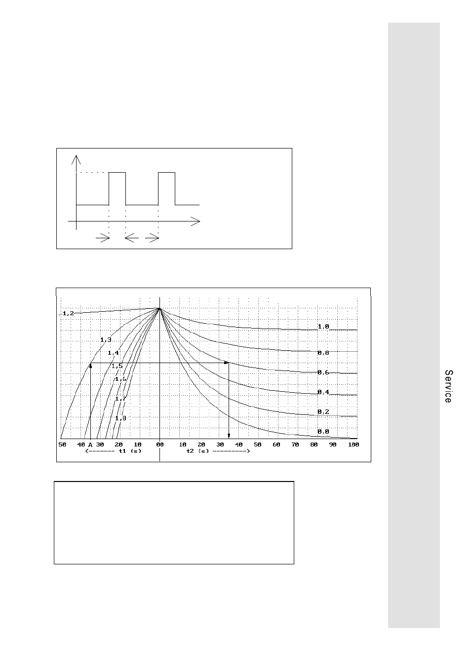
OC5 Overload axis module (I · t)
The servo controllers can be overloaded up to their peak current
for a certain period of time. The possible duration of overload
without Trip setting depends on its intensity. When exceeding
the time limit, the fault OC5 "overload" is displayed. The
current/time ratios that do not lead to Trip setting are shown in
the overload diagrams below. These overload diagrammes
show permissible overcurrents, necessary recovery times and
load cycles. Take into consideration that the rated currents of
the axis modules depend on the chopper frequency set under
C018 (see Technical data, page 6).
I
1
I
2
t
1
t
2
I1 > I
nom
: overload current
I2 < I
nom
: base load current
t1: duration of the overload
t2: duration of the base load
Overload chart for f
chop
= 8 kHz
Parameter I1/Irated
Parameter I2/Irated
Example A
given:
f
chop
= 8kHz
overload I1 = 1,3 . I
rated
,t1 = 35s
base load I2 = 0,6 . I
rated
required:
minimum duration of the base load t2
result:
t2 = 35s