Lenze 9228E User Manual
Page 17
15
Multi drive networking
•
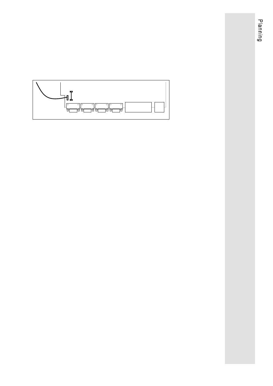
When laying the ground cables, care must be taken that there
are no ground loops. To ensure this, the GND-PE connection
must be removed in every drive. For the 9200 drives, turn the
four screws on the cover one haft turn CCW and pull out the
control board. Remove the jumper PE-BR on the board 9220
MP. CAUTION: Ensure that the mains has been disconnected
and the drive has been switched off at least 5 minutes before
removing any parts.
BR-PE
PE cable
Control board 9220MP
SubD-plugs
X1
X2
X3
X4
X5
X6
Control terminals
•
All ground cables must then be lead to external, insulated
central points, centralized again from there and connected to
PE in the central supply. The PE-GND reference is necessary
as the electronics insulation (SubD plug) does not allow
voltages >50V~ AC at PE.
•
In case of firmly installed computer connections, a mains
isolation (e.g. Lenze Converter 2101) is mandatory between
computer and axis module.
•
The individual cable screens must be connected to external
insulated centreal points, which are then connected to the PE
potential at one point.
•
The screens of the motor cables
−
should be as large as possible.
−
should be connected to the two sides.