2 electrical installation, 1 network topology, Electrical installation – Lenze E84DGFCT User Manual
Page 21: Network topology, Communication manual 8400 motec ethercat, Msd sd sd
EDS84DMOTECAT EN 2.1 - 11/2012
L
21
Communication manual 8400 motec EtherCAT®
Installation
Electrical installation
5.2
Electrical installation
5.2.1
Network topology
An EtherCAT telegram is sent through a pair of wires from the master to the slaves. The
telegram is forwarded from slave to slave until it has passed through all the devices.
Finally, the last slave returns the telegram to the master through a second pair of wires. In
this way, EtherCAT always forms a logic ring topology, independent of the topology
selected.
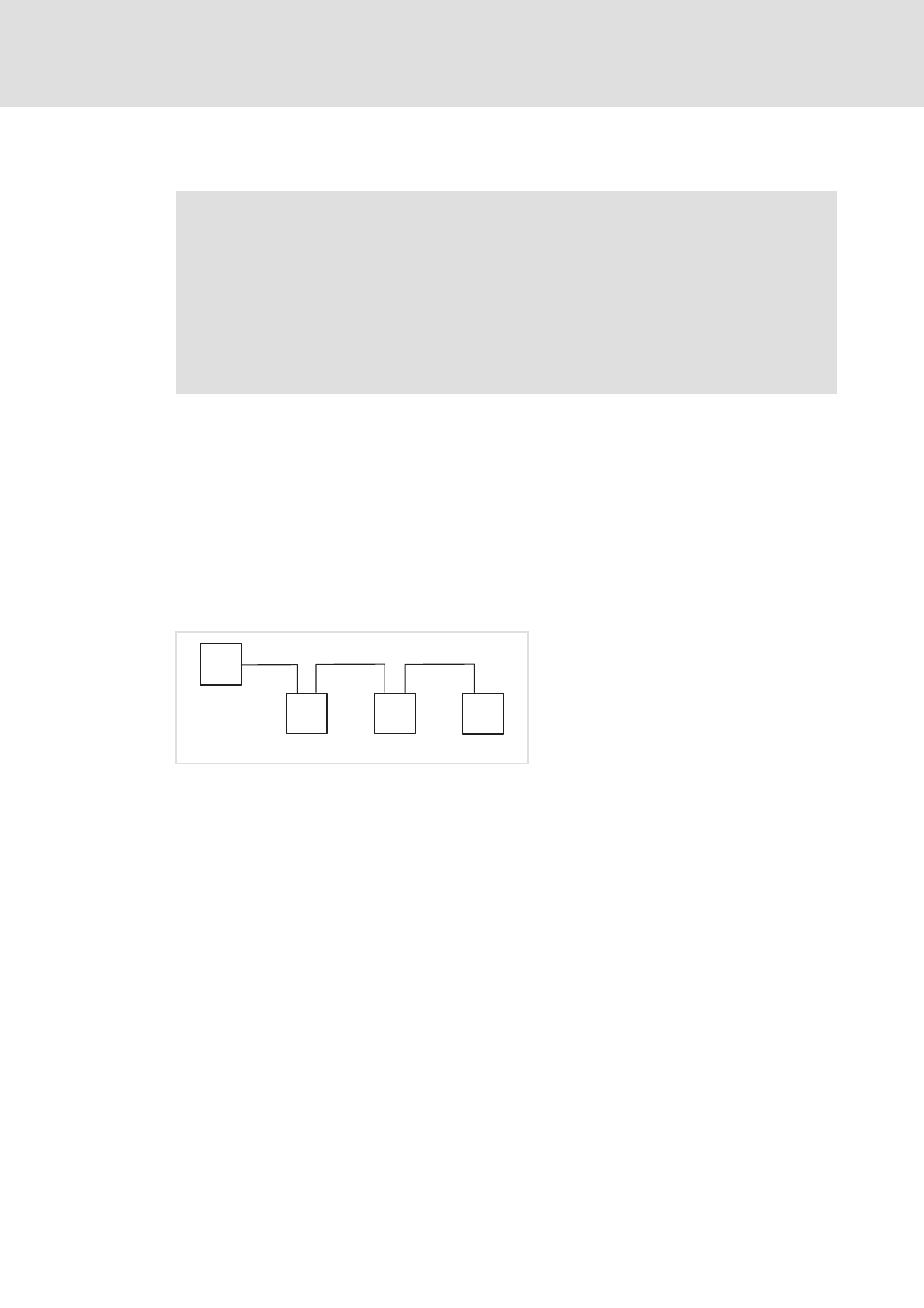
Line topology
[5-2]
Line topology
The devices are interconnected successively.
Correct assignment and wiring of the EtherCAT inputs (IN) and EtherCAT outputs (OUT)
is required for proper operation.
The direction of data transmission is from the master to the slaves.
Tip!
The termination of the last node is effected automatically by the slave.
"Inverter Drives 8400 motec" hardware manual
Here you will find detailed information about ...
• the digital and analog inputs/outputs;
• the relay output;
• the integrated safety system (safety option);
• the wiring of the connections.
Observe the notes and wiring instructions included.
E94AYCET006
M = master
SD = slave device
M
SD
SD
SD
IN
IN
OUT
IN
OUT